$34
1991 Komatsu Dresser 410 & 610 Series Engine Shop Manual – PDF DOWNLOAD
1991 Komatsu Dresser 410 & 610 Series Engine Shop Manual – PDF DOWNLOAD
FILE DETAILS:
1991 Komatsu Dresser 410 & 610 Series Engine Shop Manual – PDF DOWNLOAD
Language : English
Pages : 404
Downloadable : Yes
File Type : PDF
Size: 63.2 MB
IMAGES PREVIEW OF THE MANUAL:
DESCRIPTION:
1991 Komatsu Dresser 410 & 610 Series Engine Shop Manual – PDF DOWNLOAD
- The 1991 Komatsu Dresser 410 & 610 Series Engine Shop Manual is a comprehensive guide that provides detailed information on the maintenance, repair, and overhaul of the engines used in the Komatsu Dresser 410 and 610 series of industrial wheel loaders. This manual is intended for use by mechanics, technicians, and individuals who are knowledgeable in engine repair.
- The manual is organized into several sections, each covering a different aspect of the engine. The first section provides an overview of the engine and its components, including the specifications and performance data. This section also includes a table of contents, a list of illustrations, and a list of symbols and abbreviations used throughout the manual.
- The second section of the manual covers engine inspection and measurement procedures. This section provides step-by-step instructions for checking and measuring various components of the engine, including the cylinder block, crankshaft, and connecting rods. The manual includes detailed illustrations to help the reader understand the procedures.
- The third section covers engine disassembly and assembly procedures. This section provides instructions for removing and installing various components of the engine, including the cylinder head, pistons, and crankshaft. The manual also includes torque specifications for each component.
- The fourth section covers engine testing and adjusting procedures. This section provides instructions for testing and adjusting various components of the engine, including the fuel injection system, the turbocharger, and the valve clearance. The manual includes detailed illustrations to help the reader understand the procedures.
- The fifth section covers engine maintenance procedures, including routine maintenance and inspections. This section provides instructions for maintaining the engine to ensure its continued performance and longevity.
- The sixth section covers engine troubleshooting and diagnosis procedures. This section provides instructions for diagnosing and troubleshooting various engine problems, including starting problems, low power output, and excessive smoke. The manual includes a troubleshooting chart and detailed illustrations to help the reader diagnose and fix the problem.
- Overall, the 1991 Komatsu Dresser 410 & 610 Series Engine Shop Manual is a comprehensive guide that provides detailed information on the maintenance, repair, and overhaul of the engines used in the Komatsu Dresser 410 and 610 series of industrial wheel loaders. It is an essential tool for anyone working on or maintaining these engines. The manual is available in print or digital formats, making it a convenient and accessible resource for mechanics and technicians.
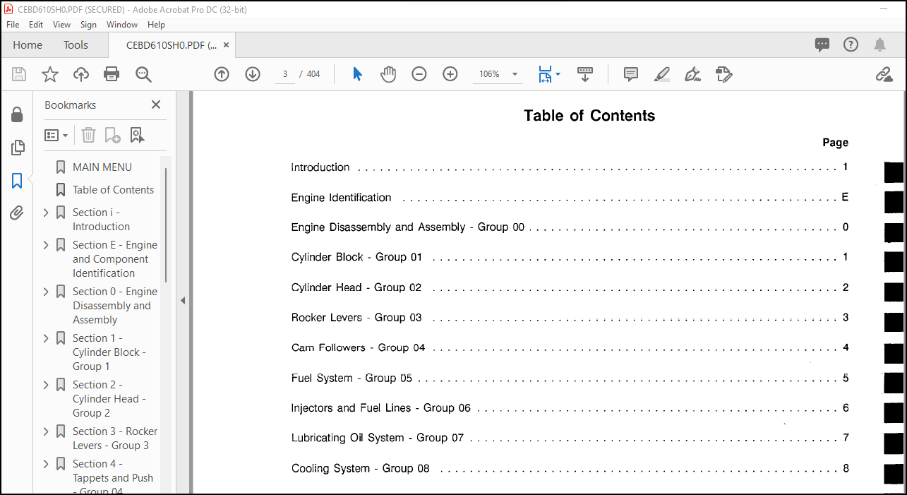
TABLE OF CONTENTS:
1991 Komatsu Dresser 410 & 610 Series Engine Shop Manual – PDF DOWNLOAD
MAIN MENU………………………………………………….. 0
Table of Contents…………………………………………… 3
Section i – Introduction…………………………………….. 5
About the Manual ……………………………………….. 6
General Cleaning Instructions ……………………………. 12
Solvent and Acid Cleaning…………………………….. 12
Steam Cleaning………………………………………. 12
General Repair Instructions ……………………………… 11
General Safety Instructions …………………………….. 10
Generic Symbols ………………………………………… 8
Glossary of Terms ………………………………………. 13
How To Use This Manual ………………………………….. 7
Group Contents………………………………………. 7
Index………………………………………………. 7
Metric Information…………………………………… 7
Table of Contents……………………………………. 7
Illustrations ………………………………………….. 9
Section E – Engine and Component Identification………………… 15
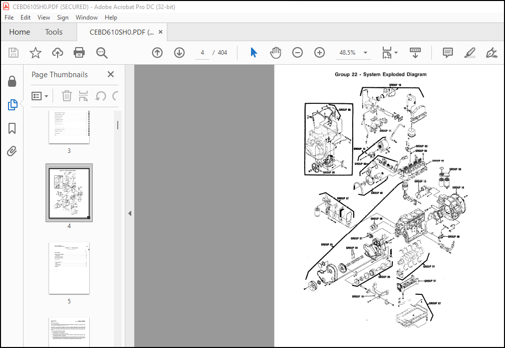
Engine Diagram …………………………………………. 20
Engine Identification …………………………………… 16
Engine Dataplate ……………………………………. 16
Injection Pump Dataplate ………………………………… 17
Cooling System………………………………………. 19
Fuel System…………………………………………. 19
General Engine Data………………………………….. 18
Intake Air and Exhaust System…………………………. 19
Lubrication System…………………………………… 18
Lucas CAV DPA dataplate location………………………. 17
Robert Bosch VE dataplate location…………………….. 17
Section 0 – Engine Disassembly and Assembly……………………. 23
Accessories – Installation ………………………………. 97
Accessories – Removal……………………………………. 44
Alternator – Installation…………………………………119
Alternator – Removal ……………………………………. 33
Balancer – Installation …………………………………. 77
Balancer – Removal ……………………………………… 53
Locking the Balancer…………………………………. 54
Measuring Backlash…………………………………… 53
Measuring the End Play……………………………….. 54
Removing the Balancer………………………………… 55
Belt Tensioner – Installation ……………………………118
Belt Tensioner – Removal…………………………………. 32
Camshaft – Installation …………………………………. 72
Camshaft End Play – Measuring…………………………. 74
Camshaft Gear Backlash – Measuring…………………….. 74
Camshaft – Removal ……………………………………… 49
Measuring Gear Lash………………………………….. 49
Crankshaft End Play – Measuring ………………………….. 83
Crankshaft – Installation ……………………………….. 61
Crankshaft – Removal ……………………………………. 58
Cylinder Block – Prepare for Assembly ……………………. 60
Cylinder Block – Removing From the Rollover Stand ………….. 60
Cylinder Head – Installation ……………………………..102
Cylinder Head – Removal …………………………………. 42
Cylinder Head – Tightening………………………………..104
Dipstick – Removal………………………………………. 39
Drive Belt – Installation ………………………………..120
Drive Belt – Removal ……………………………………. 31
Engine Assembly ………………………………………… 60
Engine Disassembly ……………………………………… 30
Engine Disassembly and Assembly ………………………….. 26
Assembly……………………………………………. 26
Disassembly…………………………………………. 26
General Information………………………………….. 26
Engine Disassembly and Assembly – Service Tools ……………. 27
Engine Disassembly Check List ……………………………. 29
Engine Weight ………………………………………….. 30
Exhaust Manifold – Installation …………………………..113
Exhaust Manifold – Removal ………………………………. 36
Fan Hub – Installation …………………………………..118
Fan Hub – Removal……………………………………….. 33
Fan Pulley – Removal ……………………………………. 32
Flywheel Housing – Installation ………………………….. 98
Flywheel Housing – Removal ………………………………. 44
Flywheel – Installation …………………………………. 98
Flywheel – Removal ……………………………………… 44
Front Cover – Installation ……………………………….100
Front Cover – Removal …………………………………… 43
Fuel Filter Head – Installation……………………………112
Fuel Filter Head – Removal ………………………………. 36
Fuel Filter – Removal …………………………………… 36
Fuel Lines – Installation ………………………………..110
Fuel Drain Manifold – Installation……………………..111
High Pressure Fuel Lines – Installation…………………111
Injection Pump Supply Line – Installation……………….110
Injection Pump Vent Line – Installation…………………111
Fuel Lines – Removal ……………………………………. 37
Fuel Drain Manifold – Removal…………………………. 38
High Pressure Fuel Line – Removal……………………… 37
Low Pressure Fuel Lines – Removal……………………… 38
Fuel Transfer Pump – Installation ………………………… 86
Fuel Transfer Pump – Removal……………………………… 47
Gear Housing – Installation ……………………………… 69
Gear Housing – Removal ………………………………….. 53
Injection Pump – Installation …………………………… 87
Injection Pumps – Unlocking…………………………… 90
Locked Timed Injection Pump – installation……………… 89
Unlocked Bosch VE Injection Pump Installation…………… 93
Unlocked CAV Injection Pump – Installation……………… 92
Injection Pump – Removal (Rotary Type Pumps) ……………… 44
Drive Gear – Removal…………………………………. 46
Gear Lash – Check……………………………………. 45
Locking the Pump…………………………………….. 45
Injector Nozzles – Installation …………………………..108
Injector Nozzles – Removal……………………………….. 40
Lifting Bracket Removal – Rear …………………………… 31
Lube Pump – Installation ………………………………… 70
Lube Pump – Removal …………………………………….. 51
Measuring Backlash…………………………………… 51
Manifold Cover – Installation …………………………….110
Manifold Cover – Removal ………………………………… 39
Aftercooler – Removal………………………………… 40
Oil Cooler – Installation ……………………………….. 85
Oil Cooler – Removal ……………………………………. 48
Oil – Draining …………………………………………. 31
Oil Filter – Installation ………………………………..121
Oil Pan – Installation ………………………………….. 85
Oil Pan Sealing Surfaces – Sealants……………………. 85
Oil Pan – Removal ………………………………………. 48
Piston and Rod Assemblies – Installation ………………….. 65
Piston and Rod Assemblies – Removal ……………………… 55
Push Rods – Installation………………………………….102
Push Rods – Removal …………………………………….. 42
Rear Seal Housing – Removal ……………………………… 49
Rear Seal – Installation…………………………………. 83
Rocker Levers – Installation ……………………………..103
Rocker Levers – Removal …………………………………. 41
Rollover Stand – Engine Mounting …………………………. 30
Rollover Stand – Engine Removal …………………………..121
Side Oil Fill – Installation …………………………….. 86
Side Oil Fill – Removal …………………………………. 47
Starter – Installation …………………………………..121
Starter – Removal ………………………………………. 30
Steam Cleaning The Engine ……………………………….. 30
Suction Tube – Installation ……………………………… 84
Suction Tube – Removal ………………………………….. 49
Tappet Cover – Installation ……………………………… 86
Tappet Cover – Removal…………………………………… 47
Thermostat – Installation ………………………………..117
Thermostat – Removal ……………………………………. 34
Timing Pin Housing – Removal …………………………….. 52
Timing Pin – Installation………………………………… 74
Turbocharger Drain Tube – Removal ……………………….. 59
Turbocharger – Installation ………………………………114
Turbocharger – Removal ………………………………….. 34
Valve Clearance – Adjustment ……………………………..106
Valve Covers – Installation ………………………………109
Valve Covers – Removal…………………………………… 40
Valve Tappets – Installation …………………………….. 60
Valve Tappets – Removal …………………………………. 51
Vibration Damper/Crankshaft Pulley – Removal………………. 32
Vibration Damper – Installation …………………………..118
Water Inlet Connection – Installation ……………………..119
Water Inlet Connection – Removal …………………………. 48
Water Pump – Installation ………………………………. 99
Water Pump – Removal ……………………………………. 43
Section 1 – Cylinder Block – Group 1…………………………..123
Balancer – Assembly ……………………………………..171
Balancer – Disassembly……………………………………169
Camshaft and Gear – Inspection ……………………………151
Camshaft Lobe Edge Deterioration (Breakdown)Criteria …….153
Camshaft Lobe Pitting Reuse Criteria …………………..152
Camshaft Bushing – Installation …………………………..145
Camshaft – Cleaning ……………………………………..151
Camshaft Expansion Plug – Installation …………………….144
Camshaft Gear – Replacement ………………………………156
Camshaft Gear – Installation (Heated Gear Method) ………156
Camshaft Gear – Installation (With Special Tool 3823589)….158
Camshaft Gear – Removal ………………………………156
Connecting Rod – Inspection ………………………………164
Crankshaft – Cleaning…………………………………….147
Crankshaft Gear – Replacement……………………………..149
Crankshaft – Inspection ………………………………….148
Cylinder Block – Cleaning…………………………………134
Cylinder Block – De-Glazing……………………………….139
Cylinder Block – Disassembly………………………………132
Cylinder Block – Exploded View…………………………….126
Cylinder Block – General Information……………………….129
Camshaft…………………………………………….129
Crankshaft…………………………………………..129
Cylinder Block……………………………………….129
Oil Seals……………………………………………129
Pistons……………………………………………..129
Vibration Damper……………………………………..129
Cylinder Block Group Inspection Checklist…………………..131
Cylinder Block – Inspection……………………………….137
Cylinder Block – Precheck Before Disassembly………………..132
Cylinder Block – Service Tools…………………………….130
Cylinder Block – Storing………………………………….147
Data Plate – Replacement………………………………….179
Dipstick Tube – Replacement……………………………….146
Expansion and Pipe Plug – Installation …………………….142
Fuel Pump Stud – Replacement ……………………………..179
Gear Housing and Timing Pin Assembly – Inspection ………….178
Gear Housing – Disassembly ……………………………….178
Piston and Connecting Rod – Assembly ………………………165
Piston and Connecting Rod – Disassembly …………………..161
Piston Inspection ……………………………………….163
Piston, Pin and Connecting Rod – Cleaning …………………162
Piston Pin – Inspection…………………………………..164
Piston Ring Gap – Checking ……………………………….167
Piston Rings – Installation ………………………………167
Rod Bearing Clearance – Checking ………………………….165
Vibration Damper – Cleaning and Inspection ………………..161
Section 2 – Cylinder Head – Group 2……………………………181
Cup Plug Replacement …………………………………….193
Cylinder Head – Assembly………………………………….201
Cylinder Head – Cleaning …………………………………187
Cylinder Head Combustion Face Inspection ………………….191
Cylinder Head Cracks – Reuse Guidelines ……………………192
Cylinder Head – Disassembly………………………………186
Cylinder Head – Precheck Before Disassembly ………………186
Cylinder Head – Service Tools …………………………….182
Exploded View …………………………………………..184
General Information ……………………………………..185
Valve Guide Inspection …………………………………..191
Valve – Inspection ………………………………………189
Valve Seat Inspection ……………………………………191
Valve Seats – Grinding …………………………………..196
Calculating the Grinding Depth ………………………..196
Measuring the Valve Depth …………………………….196
Valve Spring Inspection…………………………………..192
Valves – Grinding ……………………………………….195
Section 3 – Rocker Levers – Group 3……………………………203
Rocker Lever Assembly – Exploded View ……………………..204
Rocker Lever Assembly – General Information ………………..206
Rocker Lever – Inspection ………………………………..208
Rocker Lever Pedestals – Inspection ……………………….209
Rocker Levers and Pedestals – Cleaning ……………………208
Rocker Levers – Assembly …………………………………209
Rocker Levers – Disassembly ……………………………..207
Section 4 – Tappets and Push – Group 04………………………..211
Push Rods – Inspection……………………………………214
Tappets and Push Rods – Exploded View ……………………..212
Tappets and Push Rods – General Information ……………….213
Valve Tappets – Inspection ……………………………….214
Section 5 – Fuel System – Group 05…………………………….217
Exploded View – Fuel System ………………………………220
Injection Pump – General Information ………………………221
Injection Pump – Identification …………………………..221
Injection Pump Repairs – Bosch VE …………………………221
Delivery Valve Holder/Sealing Washer – Replacement……….222
Fuel Inlet Adapter/Seal – Replacement…………………..226
Overflow Adapter/Sealing Ring – Replacement……………..225
Shaft Seal – Replacement ……………………………..221
Shutdown Lever/Spring – Replacement…………………….224
Shutdown Solenoid – Replacement ……………………….223
Injection Pump Repairs – Lucas CAV DPA ……………………231
Automatic Timing Advance – Disassembly …………………239
Back Leakage Valve – Replacement/Inspection……………..232
Bleed Screws/Sealing Washers – Replacement………………234
Control Lever – Replacement …………………………..237
Fuel Inlet Fitting/Sealing Washer – Replacement………….236
Locking Screw/O-Ring – Replacement …………………….231
Shutdown Lever/Spring – Replacement ……………………238
Shutdown Solenoid – Replacement ……………………….233
Timing Advance – Assembly …………………………….241
Timing Advance Components – Inspection …………………241
Vent Fitting/Sealing Washer – Inspection/Replacement……..235
Injection Pump – Service Tools ……………………………218
Injection Pump Timing – Bosch VE…………………………..227
Section 6 – Injectors – Group 06………………………………247
Exploded View – Fuel System ………………………………249
Fuel Lines – Clean and Inspect ……………………………262
Fuel Drain Manifold ………………………………….263
High Pressure Fuel Lines ……………………………..262
Low Pressure Fuel Lines ………………………………264
Fuel Transfer Pump – Cleaning and Inspecting ………………259
Fuel Transfer Pump – General Information …………………..251
Fuel Transfer Pump – Identification ……………………251
Fuel Transfer Pump – Piston Style Rebuild …………………260
Assembly ……………………………………………261
Cleaning ……………………………………………261
General Information – Injectors …………………………..250
Injector – Assembly ……………………………………..256
Injector – Clean and Inspect ……………………………..254
Injector – Disassembly …………………………………..253
Injector Pump – Service Tools …………………………….248
Injector – Testing ………………………………………258
Chatter Test…………………………………………259
Section 7 – Lubrication Oil System – Group 7……………………267
Filter Bypass Valve – Replace …………………………….274
General Information – Lubrication System …………………..272
Oil Cooler Core ……………………………………..272
Lubricating Oil Cooler – Exploded View …………………….271
Lubricating Oil Pump – Exploded View ………………………276
Lubrication Oil Pump – General Information …………………277
Oil Cooler – Cleaning ……………………………………274
Oil Cooler – Inspection ………………………………….275
Oil Pan and Suction Tube – Cleaning and Inspection …………270
Oil Pan and Suction Tube – Exploded View …………………..268
Oil Pan and Suction Tube – General Information ……………..269
Oil Pump – Inspection ……………………………………278
Pressure Regulator Valve – Assembly ……………………….274
Pressure Regulator Valve – Disassembly …………………….273
Pressure Regulator Valve – Inspection …………………….273
Section 8 – Cooling System – Group 8…………………………..281
Belt Tensioner and Fan Hub – Exploded View ………………..285
Belt Tensioner and Fan Hub – General Information ……………286
Belt Tensioner ………………………………………286
Belt Tensioner – Inspection ………………………………290
Fan Hub Assembly ………………………………………..288
Fan Hub – Disassembly ……………………………………287
Fan Hub – Inspection……………………………………..287
Thermostat Housing Assembly – Exploded View ………………..291
Thermostat Housing Assembly – General Information …………..292
Thermostat – Inspection ………………………………….292
Water Pump – Exploded View ………………………………282
Water Pump – General Information ………………………….283
Water Pump – Inspection …………………………………284
Section 9 – Drive Units – Group 9……………………………..293
Accessory Drive Adapter – Exploded View ……………………294
Accessory Drive Adaptor – Assembly ………………………..297
Accessory Drive Adaptor – Disassembly ……………………..296
Accessory Drive – Cleaning ……………………………….296
Accessory Drive – Inspection ……………………………..296
Drive Units – General Information …………………………295
Accessory Drive Adapter……………………………….295
Section 10 – Air Intake System – Group 10………………………299
Aftercooler – Inspection …………………………………304
Air Intake System – Exploded View …………………………300
Air Intake System – General Information ……………………302
Turbocharger – Cleaning and Inspection for Reuse ……………303
Inspection ………………………………………….303
Section 11 – Exhaust System – Group 11…………………………305
Exhaust Manifold – Exploded View ………………………….306
Exhaust Manifold Inspection……………………………….308
General Information ……………………………………..307
Exhaust Manifold …………………………………….307
Turbocharger Mounting Stud Replacement…………………….308
Section 12 – Air Equipment – Group 12………………………….309
Section 13 – Electrical Equipment – Group 13……………………311
Section 14 – Engine Testing – Group 14…………………………313
Blowby Measurement ………………………………………319
Blowby Conversion Chart (5.613 mm [0.221 in] Orifice) ……319
Engine Dynamometer Test – Engine Run-In …………………..326
Engine Dynamometer Test – Installation of the Engine ……….320
Engine Dynamometer Test – Performance Checking ……………..330
Engine – Painting ……………………………………….334
Engine Run-In Procedure “In Chassis” ……………………..333
Engine Storage – Long Term………………………………..338
Removing the Engine from Long-Term Storage ……………..340
Engine Storage – Short Term……………………………….335
Removing the Engine from Short-Term Storage …………….337
Engine Testing – Engine Side Views ………………………..316
Engine Testing – General Information ………………………318
General Engine Test Specifications …………………….318
Engine Testing – Service Tools ……………………………314
Section 16 Mounting Adaptions – Group 16……………………….345
Flywheel and Ring Gear Inspection ……………………….347
Flywheel Housing Assembly ………………………………..348
Flywheel Housing Inspection ………………………………348
Front Support – Cleaning and Inspection…………………….350
General Information ……………………………………..346
Flywheel and Ring Gear ……………………………….346
Flywheel Housing …………………………………….346
Front Support ……………………………………….346
Ring Gear Replacement ……………………………………347
Wet Clutch Application …………………………………..349
Section V – Engine Component Specifications – Group 18…………..351
Capscrew Markings and Torque Values ……………………….390
Component Specifications and Torque Values …………………356
Air Intake System ……………………………………….382
Combustion Air System ………………………………..381
Compressed Air System Torque Values ……………………382
Cylinder Block – Rebuild Specifications ………………..366
Cylinder Block – Torque Values ………………………..372
Cylinder Head – Rebuild Specifications …………………373
Cylinder Head – Torque Values …………………………375
Electrical System ……………………………………383
Engine Assembly – Capscrew Torque Values ……………….360
Engine Assembly – Specifications……………………….356
Engine Testing – Test Specifications …………………..384
Fan Hub – Specifications ……………………………..380
Fuel System …………………………………………376
Lubricating Oil System – Specifications ………………..378
Rocker Levers and Pedestals …………………………..375
Tappet and Push Rods …………………………………376
Thermostat, Coolant Operating Temperature ………………380
Drive Belt Tension ………………………………………385
Engine Component Torque Values ……………………………353
Newton-Meter to Foot-Pound Conversion Chart ………………..388
Capscrew Markings and Torque Values – U.S. Customary …….389
Pipe Plug Torque Values ………………………………….391
Specifications – General Information ………………………352
Tap-Drill – U.S. Customary & Metric ……………………….392
Weight and Measures – Conversion Factors …………………..387
Section L – Service Literature………………………………..393
Index………………………………………………………399
More products