$35
2006 Land Rover L322 Range Rover LHD Electrical Circuit Diagrams Manual – PDF DOWNLOAD
2006 Land Rover L322 Range Rover LHD Electrical Circuit Diagrams Manual – PDF DOWNLOAD
FILE DETAILS:
2006 Land Rover L322 Range Rover LHD Electrical Circuit Diagrams Manual – PDF DOWNLOAD
Language : English
Pages : 211
Downloadable : Yes
File Type : PDF
MAGES PREVIEW OF THE MANUAL:
DESCRIPTION:
2006 Land Rover L322 Range Rover LHD Electrical Circuit Diagrams Manual – PDF DOWNLOAD
VIN: 239036 onwards
Publication Part No. LRL 21 38 55 701
PREFACE
- While every effort is made to ensure accuracy, design changes to the vehicle may be made in the period between the completion of this publication and the introduction of vehicles.
- All rights reserved. No part of this publication may be reproduced, stored in a retrieval system or transmitted in any form, electronic, mechanical, recording or other means without prior written permission from Land Rover.
- Paper copies of this document are uncontrolled, always refer to the electronic source material for the latest information.
USING THIS PUBLICATION
Health and safety
Always follow health and safety guidelines, specifically those detailed in the Workshop Manual.
Using this publication
The information provided in this publication is for use only by competent, qualified auto-electricians. Good product knowledge is
assumed, as well as the ability to access and use recommended test equipment and other reference material provided.
Test equipment and other reference material
The information in this publication should be used in conjunction with the recommended test equipment; refer to Workshop Manual.
Other reference material includes: Technical Service Bulletins (TSB) and the Workshop Manual.
The Electrical Reference Library (ERL) may also prove useful since it provides detailed connector information.
Battery disconnection and reconnection
It is imperative that any information relating to battery disconnection and reconnection is followed; refer to the appropriate sections
in the Workshop Manual.
Fault Diagnosis
Always use the recommended test equipment for correct and reliable fault diagnosis, refer to the Workshop Manual.
Harness Repair
Repairs should only be undertaken for connectors where a Service Repair Kit is available; refer to the appropriate Electrical
Reference Library (ERL).
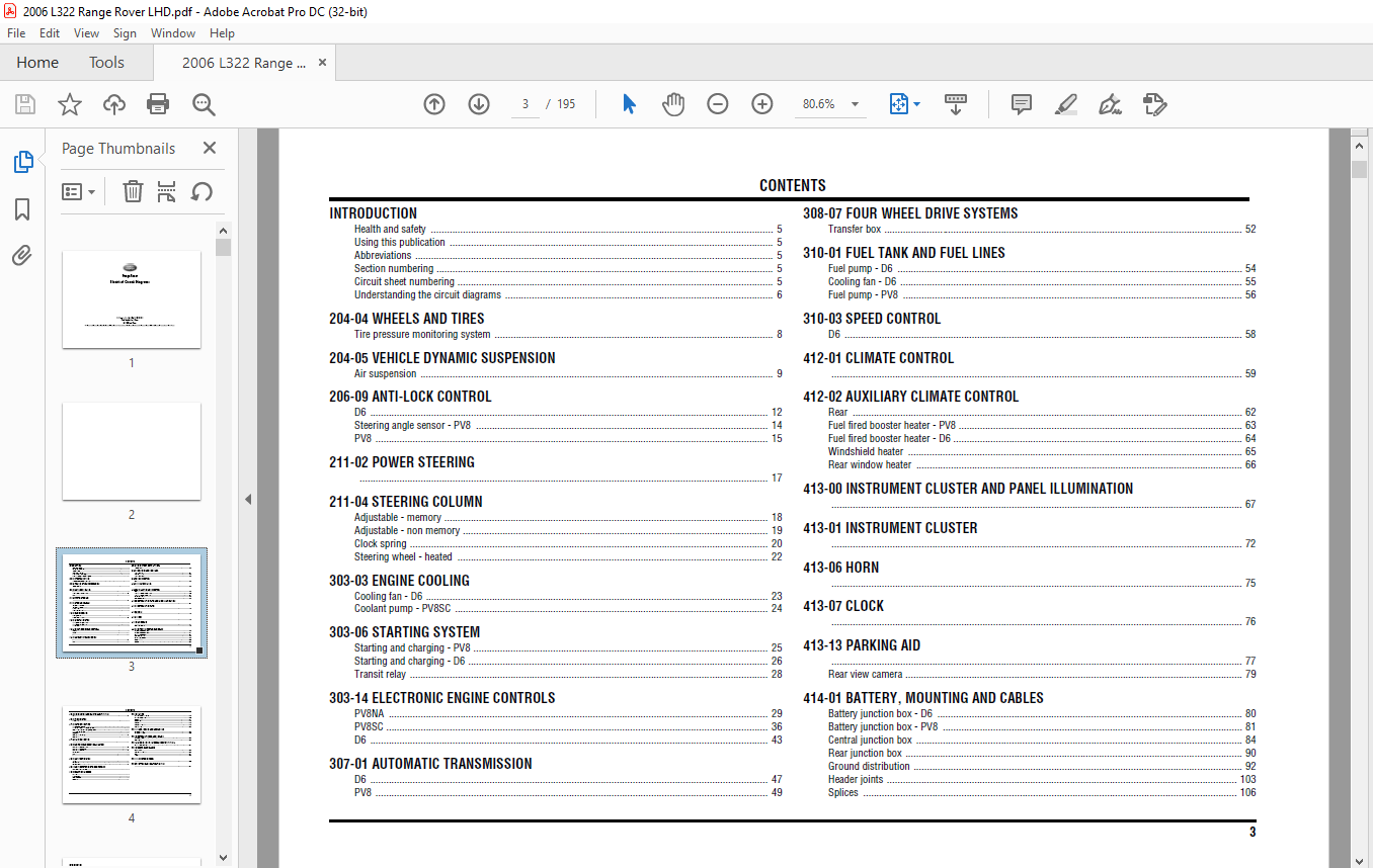
TABLE OF CONTENTS:
2006 Land Rover L322 Range Rover LHD Electrical Circuit Diagrams Manual – PDF DOWNLOAD
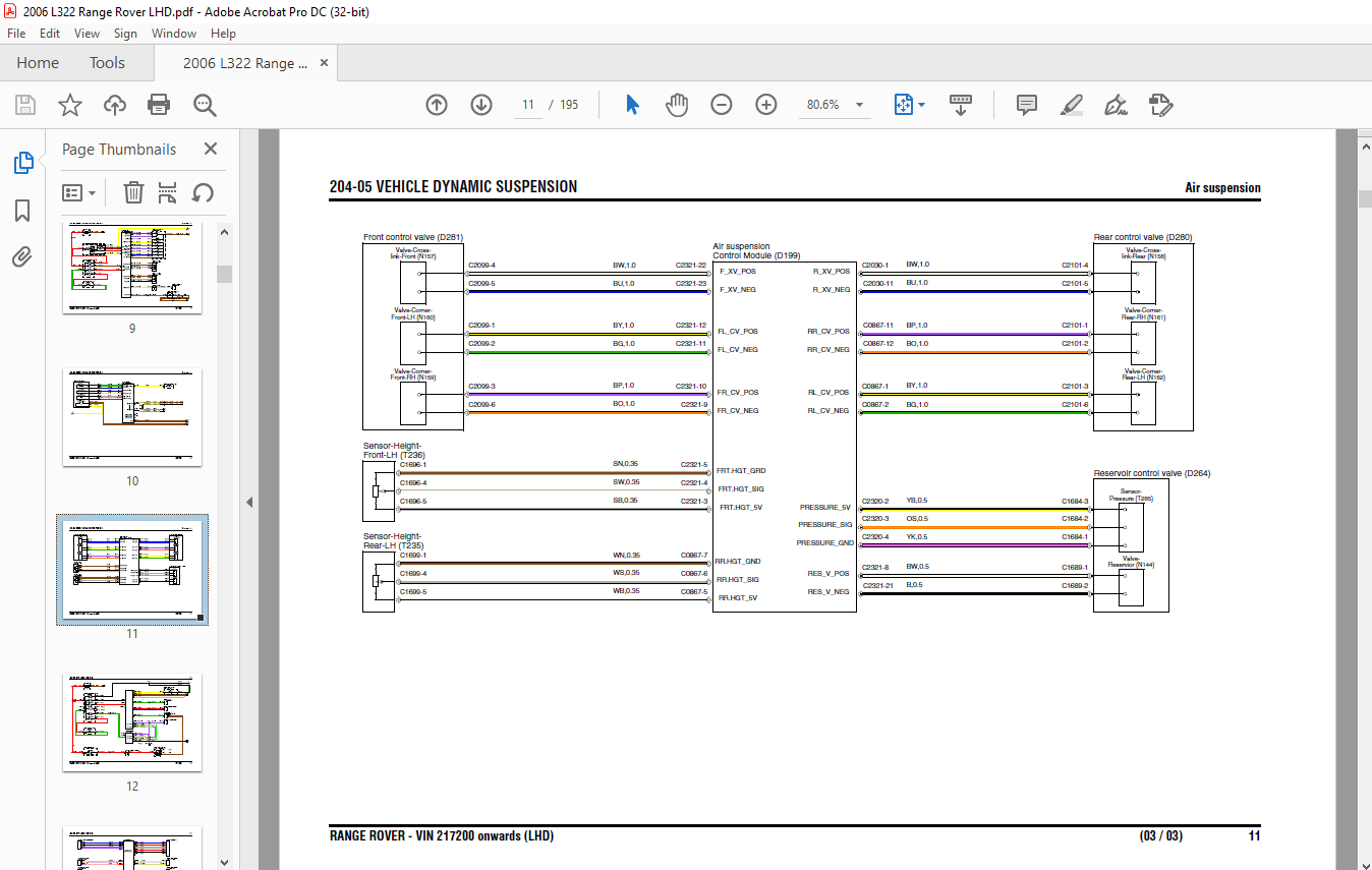
RANGE ROVER - VIN 239036 onwards (LHD)..............  1
CONTENTS............................................  3
INTRODUCTION........................................  5
	Health and safety...............................  5
	Using this publication..........................  5
	Abbreviations...................................  5
	Section numbering...............................  5
	Circuit sheet numbering.........................  5
	Understanding the circuit diagrams..............  6
204-04 WHEELS AND TIRES.............................  8
	Tire pressure monitoring system.................  8
204-05 VEHICLE DYNAMIC SUSPENSION...................  9
	Air suspension..................................  9
204-06 RIDE AND HANDLING OPTIMIZATION............... 12
	Terrain Response................................ 12
205-02 REAR DRIVE AXLE AND DIFFERENTIAL............. 13
206-05 PARKING BRAKE AND ACTUATION.................. 15
206-09 ANTI-LOCK CONTROL............................ 16
	Steering angle sensor........................... 16
	Dynamic stability control....................... 17
211-02 POWER STEERING............................... 19
211-04 STEERING COLUMN.............................. 20
	Adjustable - memory............................. 20
	Clock spring.................................... 21
	Steering wheel - heated......................... 23
303-03 ENGINE COOLING............................... 24
	Coolant pump - PV8SC............................ 24
	Cooling Fans.................................... 25
303-06 STARTING SYSTEM.............................. 26
	Starting and charging - DV8..................... 26
	Starting and charging - PV8..................... 27
	Transit relay................................... 28
303-14 ELECTRONIC ENGINE CONTROLS................... 29
	DV8............................................. 29
	PV8NA........................................... 36
	PV8SC........................................... 43
307-01 AUTOMATIC TRANSMISSION....................... 50
	Petrol.......................................... 50
	Diesel.......................................... 52
308-07 FOUR WHEEL DRIVE SYSTEMS..................... 54
	Transfer box.................................... 54
310-01 FUEL TANK AND FUEL LINES..................... 56
	Fuel pump - PV8................................. 56
	Fuel pump - DV8................................. 58
310-03 SPEED CONTROL................................ 59
412-01 CLIMATE CONTROL.............................. 60
	Front........................................... 60
	Rear - Three rotary controls.................... 63
	Rear - Two rotary controls...................... 67
412-02 AUXILIARY CLIMATE CONTROL.................... 69
	Fuel fired booster heater - DV8................. 69
	Fuel fired booster heater - PV8................. 70
	Windshield heater............................... 71
	Rear window heater.............................. 72
413-00 INSTRUMENT CLUSTER AND PANEL ILLUMINATION.... 73
413-01 INSTRUMENT CLUSTER........................... 79
413-06 HORN......................................... 82
413-07 CLOCK........................................ 83
413-13 PARKING AID.................................. 84
	Rear view camera................................ 86
414-01 BATTERY, MOUNTING AND CABLES................. 87
	Battery junction box - DV8...................... 87
	Battery junction box - PV8...................... 91
	Central junction box............................ 95
	Rear junction box...............................102
	Splices.........................................105
	Ground distribution.............................123
	Header joints...................................134
415-00 INFORMATION AND ENTERTAINMENT SYSTEM.........136
	MOST............................................136
415-07 VIDEO SYSTEM.................................150
	Companion.......................................150
417-01 EXTERIOR LIGHTING............................151
	Stop and reverse lamps..........................151
	Turn signal indicators and hazard flashers......153
	Trailer socket - Europe.........................155
	Fog lamps.......................................156
	Headlamps.......................................157
	Headlamps - cornering...........................159
	Headlamps - adaptive front lighting system......161
417-02 INTERIOR LIGHTING............................163
418-00 MODULE COMMUNICATIONS NETWORK................166
	CAN bus - high speed............................166
	CAN bus - medium speed..........................168
	K Bus, I Bus....................................169
	Diagnostic socket...............................170
419-01 ANTI-THEFT SYSTEM............................171
	Active..........................................171
	Passive - DV8...................................173
	Passive - PV8...................................174
419-10 MULTIFUNCTION ELECTRONIC MODULES.............175
	Generic electronic module.......................175
501-09 REAR VIEW MIRRORS............................178
	Non memory......................................178
	Fold back.......................................179
	Electrochromic..................................180
	Memory..........................................181
501-10 SEATING......................................182
	Lumbar support - electric.......................182
	Heated - front..................................183
	Memory..........................................184
	Non memory......................................186
	Climate.........................................188
501-11 GLASS, FRAMES AND MECHANISMS.................190
	Window lift - rear..............................190
	Window lift - front.............................191
501-12 INSTRUMENT PANEL AND CONSOLE.................193
	Accessory socket................................193
	Cigar lighter...................................194
	Switch pack - Instrument panel (center).........195
	Switch pack - Center console....................196
501-14 HANDLES, LOCKS, LATCHES AND ENTRY SYSTEMS....197
	Central locking system..........................197
	Glove compartment release.......................199
501-16 WIPERS AND WASHERS...........................200
	Front...........................................200
	Rear............................................202
	Power wash......................................203
	Washer jets - heated............................204
501-17 ROOF OPENING PANEL...........................205
501-20 SUPPLEMENTAL RESTRAINT SYSTEM................206
	Non NAS.........................................206
	NAS.............................................209
More products