$32
2009 Land Rover L320 Range Rover Sport (LHD) Electrical Wiring Diagrams Manual – PDF DOWNLOAD
2009 Land Rover L320 Range Rover Sport (LHD) Electrical Wiring Diagrams Manual – PDF DOWNLOAD
FILE DETAILS:
2009 Land Rover L320 Range Rover Sport (LHD) Electrical Wiring Diagrams Manual – PDF DOWNLOAD
Language : English
Pages :166
Downloadable : Yes
File Type : PDF
IMAGES PREVIEW OF THE MANUAL:
DESCRIPTION:
2009 Land Rover L320 Range Rover Sport (LHD) Electrical Wiring Diagrams Manual – PDF DOWNLOAD
VIN: 228498
Part No. JLR 14 93 21_1E
PREFACE
- While every effort is made to ensure accuracy, design changes to the vehicle may be made in the period between the completion of this publication and the introduction of vehicles.
- All rights reserved. No part of this publication may be reproduced, stored in a retrieval system or transmitted in any form, electronic, mechanical, recording or other means without prior written permission from Land Rover.
- Paper copies of this document are uncontrolled, always refer to the electronic source material for the latest information.
USING THIS PUBLICATION
Health and safety
Always follow health and safety guidelines, specifically those detailed in the Workshop Manual.
Using this publication
The information provided in this publication is for use only by competent, qualified auto-electricians. Good product knowledge is
assumed, as well as the ability to access and use recommended test equipment and other reference material provided.
Test equipment and other reference material
The information in this publication should be used in conjunction with the recommended test equipment; refer to Workshop Manual.
Other reference material includes: Technical Service Bulletins (TSB) and the Workshop Manual.
The Electrical Reference Library (ERL) may also prove useful since it provides detailed connector information.
Battery disconnection and reconnection
It is imperative that any information relating to battery disconnection and reconnection is followed; refer to the appropriate sections
in the Workshop Manual.
Fault Diagnosis
Always use the recommended test equipment for correct and reliable fault diagnosis, refer to the Workshop Manual.
Harness Repair
Repairs should only be undertaken for connectors where a Service Repair Kit is available; refer to the appropriate Electrical
Reference Library (ERL).
TABLE OF CONTENTS:
2009 Land Rover L320 Range Rover Sport (LHD) Electrical Wiring Diagrams Manual – PDF DOWNLOAD
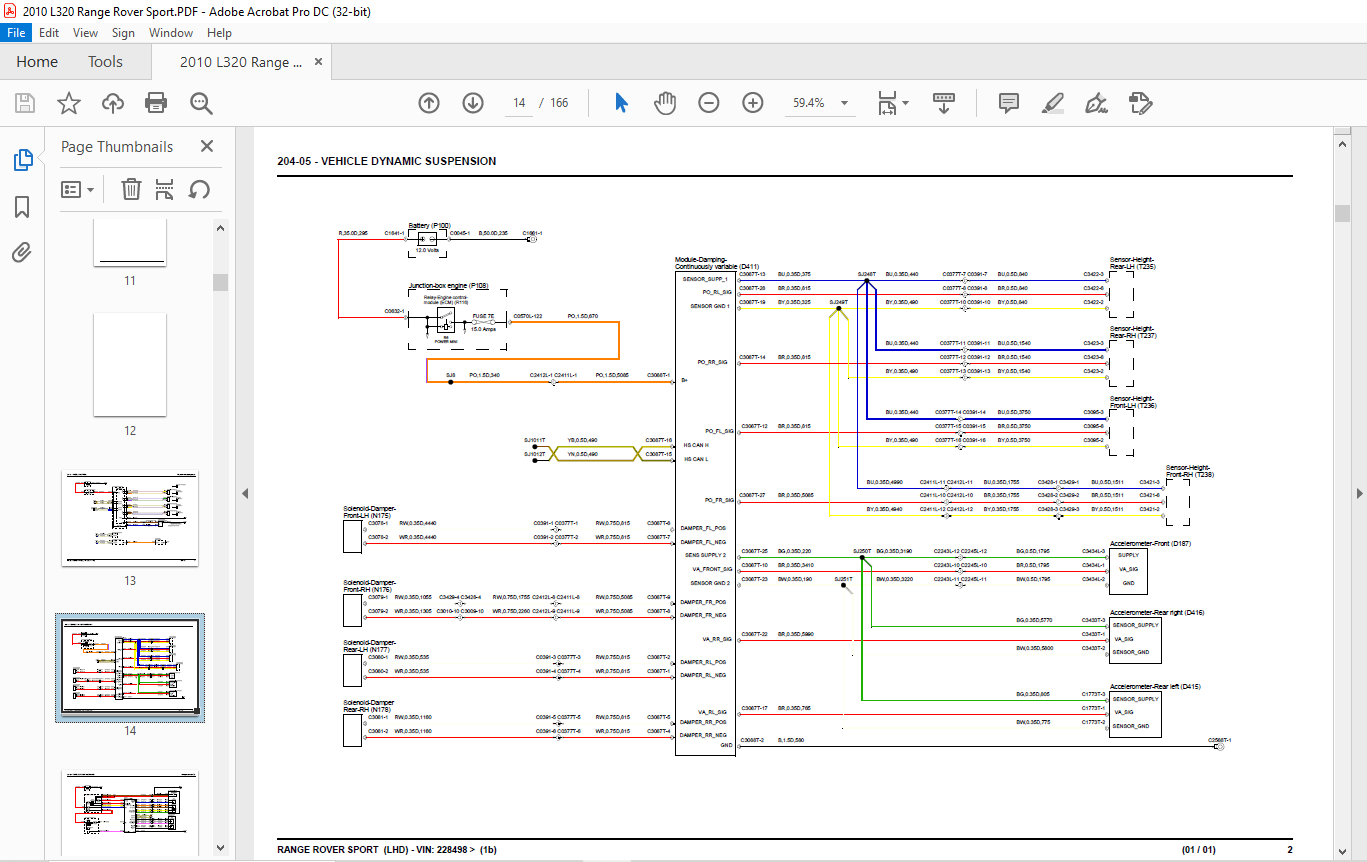
RANGE ROVER SPORT (LHD) VIN: 228498 >.................  1
	CONTENTS..........................................  5
	ABBREVIATIONS.....................................  8
	USING THIS PUBLICATION............................  9
		Health and safety.............................  9
		Using this publication........................  9
		Section numbering............................. 10
		Circuit sheet numbering....................... 10
		Understanding the circuit diagrams............ 10
204-04 - WHEELS AND TIRES............................. 13
	Tire pressure monitoring system................... 13
204-05 - VEHICLE DYNAMIC SUSPENSION................... 14
	Air suspension with CVD........................... 15
	Air suspension without CVD........................ 17
204-06 - RIDE AND HANDLING OPTIMIZATION............... 19
	Dynamic Response.................................. 19
205-02 - REAR DRIVE AXLE AND DIFFERENTIAL............. 20
206-05 - PARKING BRAKE AND ACTUATION.................. 22
206-09 - ANTI-LOCK CONTROL............................ 23
211-04 - STEERING COLUMN.............................. 25
	Adjustable........................................ 25
	Clock spring...................................... 26
303-06 - STARTING SYSTEM.............................. 28
	Ignition.......................................... 28
303-14 - ELECTRONIC ENGINE CONTROLS................... 29
	PV8............................................... 29
	DV6............................................... 34
	DV8............................................... 39
307-01 - AUTOMATIC TRANSMISSION....................... 46
	DV8............................................... 46
	DV6 and PV8....................................... 48
308-07 - FOUR WHEEL DRIVE SYSTEMS..................... 50
	Transfer box...................................... 50
310-01 - FUEL TANK AND FUEL LINES..................... 52
310-03 - SPEED CONTROL................................ 54
412-01 - CLIMATE CONTROL.............................. 55
412-02 - AUXILIARY CLIMATE CONTROL.................... 58
	Fuel fired booster heater......................... 58
	Heated screen and washer jets..................... 59
413-00 - INSTRUMENT CLUSTER AND PANEL ILLUMINATION.... 60
413-06 - HORN......................................... 62
413-07 - CLOCK........................................ 63
413-08 - INFORMATION AND MESSAGE CENTER............... 64
413-13 - PARKING AID.................................. 66
	Multiple cameras.................................. 68
	Rear view camera.................................. 69
414-01 - BATTERY, MOUNTING AND CABLES................. 70
	Engine junction box............................... 70
	Central junction box.............................. 78
	Ground distribution............................... 89
414-02 - GENERATOR AND REGULATOR...................... 97
	Diesel............................................ 97
	Petrol............................................ 98
415-00 - INFORMATION AND ENTERTAINMENT SYSTEM......... 99
	High line......................................... 99
	Portable audio interface..........................108
417-01 - EXTERIOR LIGHTING............................109
	Head, side, tail and number plate lamps...........109
	Headlamps - adaptive front lighting system........114
	Lighting control switch...........................116
	Auxiliary.........................................117
	Trailer socket - Europe...........................118
	Trailer socket - NAS..............................119
417-02 - INTERIOR LIGHTING............................120
	Ambient lighting..................................123
418-00 - MODULE COMMUNICATIONS NETWORK................124
	CAN bus - medium speed............................124
	CAN bus - high speed..............................125
	MOST..............................................127
	Diagnostic socket.................................132
419-01 - ANTI-THEFT SYSTEM............................133
	Keyless Entry.....................................133
	Passive start.....................................137
	Active............................................139
501-09 - REAR VIEW MIRRORS............................141
	Interior..........................................141
	Door..............................................142
501-10 - SEATING......................................143
	Non memory........................................143
	Memory............................................145
	Heated - front....................................148
	Heated - rear.....................................149
501-11 - GLASS, FRAMES AND MECHANISMS.................150
	Window lift.......................................150
501-12 - INSTRUMENT PANEL AND CONSOLE.................152
	Accessory socket(s)...............................152
	Cool box..........................................153
501-14 - HANDLES, LOCKS, LATCHES AND ENTRY SYSTEMS....154
	Central locking system............................154
	Tailgate power striker............................158
501-16 - WIPERS AND WASHERS...........................159
501-17 - ROOF OPENING PANEL...........................161
501-20B - SUPPLEMENTAL RESTRAINT SYSTEM...............162
More products