$45
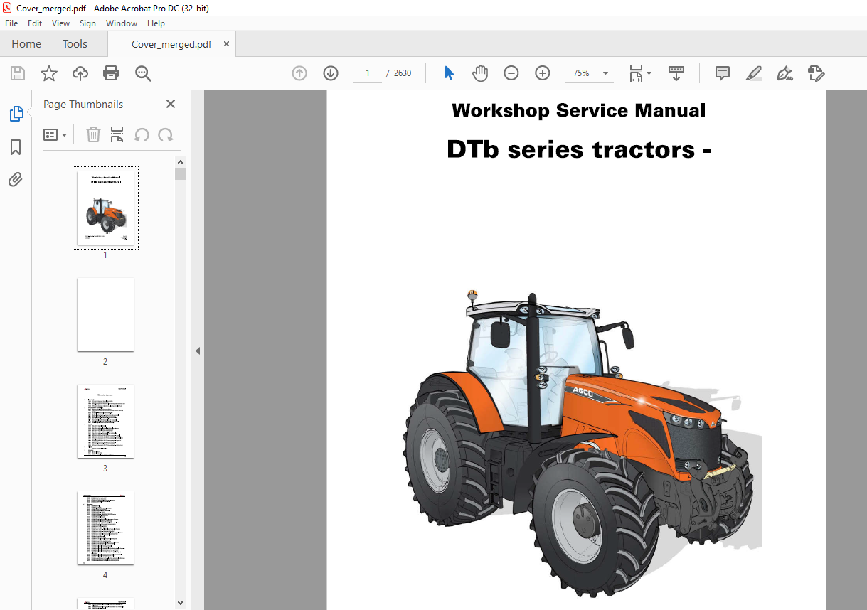
AGCO® DTb series tractors Workshop Service Manual – PDF DOWNLOAD
AGCO® DTb series tractors Workshop Service Manual – PDF DOWNLOAD
FILE DETAILS:
AGCO® DTb series tractors Workshop Service Manual – PDF DOWNLOAD
Language : English
Pages :2630
Downloadable : Yes
File Type : PDF
Size:428 MB
DESCRIPTION:
AGCO® DTb series tractors Workshop Service Manual – PDF DOWNLOAD
1 Using the manual
General The purpose of this manual is to assist Dealers and Agents in the efficient installation, servicing and repair of AGCO equipment. If the procedures are carried out as detailed and specialised tools are used where appropriate, the operations should be completed within the times stated in the repair time schedule.
Service tools
Where the use of a service tool is necessary to carry out an operation, the tool reference is mentioned with
the relevant instruction.
Tool drawings for makeshift tools are given at the end of the relevant sections.
Repairs and parts replacement
When parts have to be replaced, it is essential that only genuine AGCO parts are used.
The following points are of particular importance when carrying out repairs and fitting replacement parts and
accessories. Tractor safety may be compromised if non-genuine parts are fitted.
Legislation in certain countries prohibits the fitting of parts that do not comply with the tractor manufacturer’s
specifications. Torque wrench setting figures given in the workshop manual must be strictly adhered to.
Locking devices must be fitted where specified. If the efficiency of a locking device is impaired during disassembly,
it must be replaced.
The tractor warranty may be invalidated if non-genuine AGCO parts are fitted. All AGCO parts are guaranteed
by the manufacturer. AGCO Dealers and Agents are required to supply genuine parts only.
TABLE OF CONTENTS:
AGCO® DTb series tractors Workshop Service Manual – PDF DOWNLOAD
1 Introduction
1A10 DTb series tractors/ – General information
1A11 DTb series tractors/ – Error codes
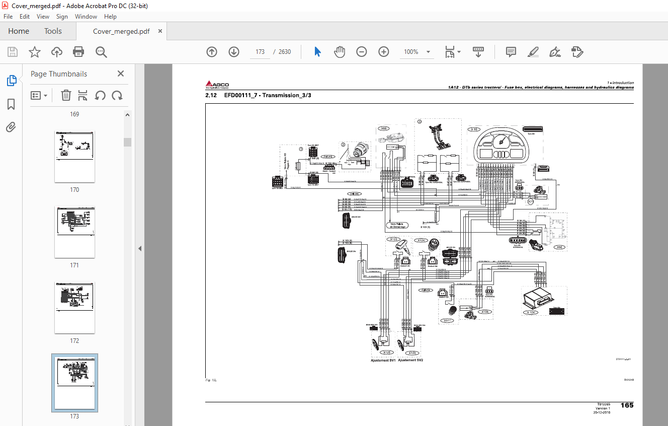
1A12 DTb series tractors/ – Fuse box, electrical diagrams, harnesses and
hydraulics diagrams
1 A 16 DTb series tractors/ – Adjustments, bleeding and calibrations
2 Separation of assemblies
2A 17 Side member – Removing and refitting
2B17 Two side members – Removing and refitting without removing
engine
2C17 Front axle – Disassembly and reassembly
2D17 Engine – Disassembly and reassembly
2E17 Engine flywheel/spacer – Disassembly and reassembly
2F17 Hydraulic spacer – Disassembly and reassembly
2G17 Rear axle/gearbox – Disassembly and reassembly
2H17 Cab – Disassembly and reassembly
2117 Rear hydraulic unit – Disassembly and reassembly
2J17 Complete hydraulic unit – Disassembly and reassembly
2K17 Front linkage – Disassembly and reassembly
3 Engine
3A 10 Sisu Tier 3 engine – General
3A11 Sisu Tier 3 engine – Error codes
3A12 Sisu Tier 3 engine – Electrical and hydraulics diagrams
3A13 Sisu Tier 3 engine – Layout of components
3A14 Sisu Tier 3 engine – Tests and diagnostics
3A16 Sisu Tier 3 engine -Adjustments, bleeding and calibrations
3A17 Sisu Tier 3 engine – Disassembly and reassembly
3A18 Sisu Tier 3 engine – Service tools
3B10 DTb series tractors, e3 SCR Technology engine – General
3B11 DTb series tractors, e3 SCR Technology engine – Error codes
3B12 DTb series tractors, e3 SCR Technology engine – Electrical and
hydraulics diagrams
3B13 DTb series tractors, e3 SCR Technology engine – Layout of
components
3B17 DTb series tractors, e3 SCR Technology engine –
Disassembly/reassembly
3B18 DTb series tractors, e3 SCR Technology engine – Service tools
4 Clutch
Chapter intentionally left blank
5 Gearbox
5A10 ML260 – General
5A11 ML260 – Error codes
5A12 ML260 – Electrical and hydraulics diagrams
3
DTb series tractors –
Table of contents
~,a.AGCO
Your Agriculture Company
ML260 – Layout of components
ML260 – Tests and diagnostics
ML260 – Adjustments, bleeding and calibrations
ML260 – Disassembly and reassembly
ML260 – Service tools
Rear axle
6A10 HA260 – General
6A11 HA260 – Error codes
6A12 HA260 – Electrical and hydraulics diagrams
6A 13 HA260 – Layout of components
6A17 HA260 – Disassembly and reassembly
6A20 HA260/Final drives – General
6A23 HA260/Final drives – Layout of components
6A27 HA260/Final drives – Disassembly and reassembly
HA260/Final drives – Service tools
HA260/Differential – General
HA260/Differential – Error codes
HA260/Differential – Electrical and hydraulics diagrams
HA260/Differential – Layout of components
HA260/Differential – Tests and diagnostics
HA260/Differential – Adjustments, bleeding and calibrations
HA260/Differential – Disassembly and reassembly
HA260/Differential – Service tools
HA260/Tractor braking – General
HA260/Tractor braking – Error codes
HA260/Tractor braking – Electrical and hydraulics diagrams
HA260/Tractor braking – Layout of components
HA260/Tractor braking – Tests and diagnostics
HA260/Tractor braking – Adjustments, bleeding and calibrations
HA260/Tractor braking – Disassembly and reassembly
HA260/Tractor braking – Service tools
HA260/ParkLock – General
HA260/ParkLock – Error codes
HA260/ParkLock – Electrical and hydraulics diagrams
HA260/ParkLock – Layout of components
HA260/ParkLock – Tests and diagnostics
HA260/ParkLock – Adjustments, bleeding and calibrations
HA260/ParkLock – Disassembly and reassembly
HA260/ParkLock – Service tools
HA260/Hydraulic trailer braking – General
HA260/Hydraulic trailer braking – Error codes
HA260/Hydraulic trailer braking – Electrical and hydraulics diagrams
HA260/Hydraulic trailer braking – Layout of components
HA260/Hydraulic trailer braking – Tests and diagnostics
HA260/Hydraulic trailer braking – Adjustments, bleeding and
calibrations
HA260/Hydraulic trailer braking – Disassembly and reassembly
HA260/Hydraulic trailer braking – Service tools
HA260/Pneumatic trailer braking – General
HA260/Pneumatic trailer braking – Electrical and hydraulics diagrams
HA260/Pneumatic trailer braking – Layout of components
HA260/Pneumatic trailer braking – Tests and diagnostics
~.. .A GCO
Your Agriculture Company
DTb series tractors –
Table of contents
6A76 HA260/Pneumatic trailer braking – Adjustments, bleeding and
calibrations
6A77 HA260/Pneumatic trailer braking – Disassembly and reassembly
6A80 HA260/Auto-hitch – General
6A82 HA260/Auto-hitch – Electrical and hydraulics diagrams
6A83 HA260/Auto-hitch – Layout of components
6A86 HA260/Auto-hitch – Adjustments, bleeding and calibrations
6A90 HA260/Wheels and hub – General
6A93 HA260/Wheels and hub – Layout of components
6A96 HA260/Wheels and hub – Adjustments, bleeding and calibrations
7 Power take-off
7 A 10 HA260/Power take-off – General
7 A 11 HA260/Power take-off – Error codes
7A12 HA260/Power take-off- Electrical and hydraulics diagrams
7 A 13 HA260/Power take-off – Layout of components
7A14 HA260/Power take-off – Tests and diagnostics
7 A 16 HA260/Power take-off – Adjustments, bleeding and calibrations
7A17 HA260/Power take-off- Disassembly and reassembly
7 A 18 HA260/Power take-off – Service tools
7810 Zuidberg front power take-off – General
7812 Zuidberg front power take-off – Electrical and hydraulics diagrams
7813 Zuidberg front power take-off – Layout of components
7814 Zuidberg front power take-off – Tests and diagnostics
7816 Zuidberg front power take-off – Adjustments, bleeding and
calibrations
7817 Zuidberg front power take-off – Disassembly and reassembly
8 Front axle
8A 10 DANA770 – General
8A 11 DANA770 – Error codes
8A12 DANA770 – Electrical and hydraulics diagrams
8A 13 DANA770 – Location of components – Front axle
8A14 DANA770 – Tests and diagnostics
8A 16 DANA770 – Adjustments, bleeding and calibrations
8A17 DANA770 – Disassembly and reassembly
8A 18 DANA770 – Service tools
8817 Bearings and transmission shaft – Disassembly and reassembly
8C10 4WD clutch – General
8C11 4WD clutch – Error codes
8C12 4WD clutch – Electrical and hydraulics diagrams
8C13 4WD clutch – Layout of components
8C14 4WD clutch – Tests and diagnostics
8C16 4WD clutch – Adjustments, bleeding and calibrations
8C17 4WD clutch – Disassembly and reassembly
8D10 Steering unit – General
8D12 Steering unit – Electrical and hydraulics diagrams
8D13 Steering unit – Layout of components
8D14 Steering unit – Tests and diagnostics
8D17 Steering unit – Disassembly and reassembly
9 Hydraulics
9A 10 LS hydraulic system – General
9A12 LS hydraulic system – Electrical and hydraulics diagrams
LS hydraulic system – Layout of components
LS hydraulic system – Tests and diagnostics
LS hydraulic system – Service tools
LS hydraulic system/Hydraulic pumps – General
LS hydraulic system/Hydraulic pumps – Electrical and hydraulics
diagrams
LS hydraulic system/Hydraulic pumps – Layout of components
LS hydraulic system/Hydraulic pumps – Tests and diagnostics
LS hydraulic system/Hydraulic pumps – Disassembly and reassembly
LS hydraulic system/Hydraulic pumps – Service tools
LS hydraulic system/Auxiliary spool valves – General
LS hydraulic system/Auxiliary spool valves – Error codes
LS hydraulic system/Auxiliary spool valves- Electrical and hydraulics
diagrams
LS hydraulic system/Auxiliary spool valves – Layout of components
LS hydraulic system/Auxiliary spool valves – Tests and diagnostics
LS hydraulic system/Auxiliary spool valves – Disassembly and
reassembly
LS hydraulic system/Auxiliary spool valves – Service tools
LS hydraulic system/Rear linkage – General
LS hydraulic system/Rear linkage – Error codes
LS hydraulic system/Rear linkage – Electrical and hydraulics
diagrams
LS hydraulic system/Rear linkage – Layout of components
LS hydraulic system/Rear linkage – Tests and diagnostics
LS hydraulic system/Rear linkage – Adjustments, bleeding and
calibrations
LS hydraulic system/Rear linkage – Disassembly and reassembly
LS hydraulic system/Rear linkage – Service tools
LS hydraulic system/Front linkage – General
LS hydraulic system/Front linkage – Electrical and hydraulics
diagrams
LS hydraulic system/Front linkage – Layout of components
LS hydraulic system/Front linkage – Tests and diagnostics
LS hydraulic system/Front linkage – Adjustments, bleeding and
calibrations
9A57 LS hydraulic system/Front linkage – Disassembly and reassembly
9A58 LS hydraulic system/Front linkage – Service tools
Electricity
10A10 Electricity – General
1 0A 12 Electricity – Electrical and hydraulics diagrams
1 0A 13 Electricity – Layout of components
10B10 Fuse box – General
10B12 Fuse box – Diagrams and plans
10B13 Fuse box – Layout of components
10B17 Fuse box – Disassembly and reassembly
10C12 Alternator – Electrical and hydraulics diagrams
1OC13 Alternator – Layout of components
10C14 Alternator – Tests and diagnostics
1OC17 Alternator – Disassembly and reassembly
1OC18 Alternator – Service tools
10D12 Batteries – Electrical and hydraulics diagrams
~.. .A GCO
Your Agriculture Company
DTb series tractors –
Table of contents
10E10 Starter – General
10E12 Starter – Electrical and hydraulics diagrams
10E13 Starter – Layout of components
1 0E14 Starter – Tests and diagnostics
10E17 Starter – Disassembly and reassembly
1OF10 Battery isolator – – General
11 Electronics
11A10 Automatic air conditioning function – General
11B10 Power take-off function – General
11 C10 Engine function – General
11D10 Transmission function – General
11E10 ParkLock function – General
11F10 4WD function – General
11 G10 Differential lock function – General
11H10 Headlights module function – General
11110 Suspended front axle function – General
11J10 Suspended cab function – General
11K10 Auxiliary hydraulics function – General
11L10 Linkage function – General
11 M10 Vistronic function – General
11N10 SpeedSteer function – General
11012 I so bus – Electrical and hydraulics diagrams
11 P11 Auto-Guide – Error codes
11P12 Auto-Guide – Electrical and hydraulics diagrams
11010 Telemetry – General
11011 Telemetry – Error codes
11012 Telemetry – Electrical and hydraulics diagrams
11013 Telemetry – Layout of components
11015 Telemetry – Programming and setting parameters
11017 Telemetry – Disassembly and reassembly
12 Cab
12A10 Standard air conditioning – General
12A 12 Standard air conditioning – Electrical and hydraulics diagrams
12A13 Standard air conditioning – Layout of components
12A14 Standard air conditioning – Tests and diagnostics
12A 16 Standard air conditioning – Adjustments, bleeding and calibrations
12A17 Standard air conditioning – Disassembly and reassembly
12A 18 Standard air conditioning – Service tools
12B10 Self-regulating air conditioning – General
12B11 Self-regulating air conditioning – Error codes
12B12 Self-regulating air conditioning – Electrical and hydraulics diagrams
12B13 Self-regulating air conditioning – Layout of components
12B14 Self-regulating air conditioning – Tests and diagnostics
12B16 Self-regulating air conditioning – Adjustments, bleeding and
calibrations
12B17 Self-regulating air conditioning – Disassembly and reassembly
12B18 Self-regulating air conditioning – Service tools
12C10 Passive hydraulic suspension – General
12C11 Passive hydraulic suspension – Error codes
12C12 Passive hydraulic suspension – Electrical and hydraulics diagrams
12C13 Passive hydraulic suspension – Layout of components
7
DTb series tractors – ~.. .A GCO
Table of contents YourAgrlcuitu,eCompany
13
14
8
12C14 Passive hydraulic suspension – Tests and diagnostics
12C16 Passive hydraulic suspension – Adjustments, bleeding and
calibrations
12C17 Passive hydraulic suspension – Disassembly and reassembly
12D10 Semi-active hydraulic suspension – General
12D11 Semi-active hydraulic suspension – Error codes
12D12 Semi-active hydraulic suspension – Electrical and hydraulics
diagrams
12D13 Semi-active hydraulic suspension – Layout of components
12D14 Semi-active hydraulic suspension – Tests and diagnostics
12D16 Semi-active hydraulic suspension -Adjustments, bleeding and
calibrations
12D17 Semi-active hydraulic suspension – Disassembly and reassembly
12E10 Passive pneumatic suspension – General
12E11 Passive pneumatic suspension – Error codes
12E12 Passive pneumatic suspension – Electrical and hydraulics diagrams
12E13 Passive pneumatic suspension – Layout of components
12E14 Passive pneumatic suspension – Tests and diagnostics
12E16 Passive pneumatic suspension – Adjustments, bleeding and
calibrations
Passive pneumatic suspension – Disassembly and reassembly
Semi-active pneumatic suspension – General
Semi-active pneumatic suspension – Error codes
Semi-active pneumatic suspension – Layout of components
Semi-active pneumatic suspension – Tests and diagnostics
Semi-active pneumatic suspension – Adjustments, bleeding and
calibrations
12F17 Semi-active pneumatic suspension – Disassembly and reassembly
12G 10 Reverse station – General
12G11 Reverse station – Error codes
12G12 Reverse station – Electrical and hydraulics diagrams
12G13 Reverse station – Layout of components
12G14 Reverse station – Tests and diagnostics
12G16 Reverse station – Adjustments, bleeding and calibrations
12G17 Reverse station – Disassembly and reassembly
Accessories
13A12 Front-end loader – Electrical and hydraulics diagrams
Service tools
14A01 General
14A03 Engine
14A05 Gearbox
14A06 Rear axle
14A07 Power take-off
14A08 Front axle
14A09 Hydraulics
14A10 Electricity
14A12 Cab
IMAGES PREVIEW OF THE MANUAL:
More products