$33
AGCO NA Engine EURO 2 Series 1000 3-4-6 Cylinders Workshop Manual – PDF DOWNLOAD
AGCO NA Engine EURO 2 Series 1000 3-4-6 Cylinders Workshop Manual – PDF DOWNLOAD
FILE DETAILS:
AGCO NA Engine EURO 2 Series 1000 3-4-6 Cylinders Workshop Manual – PDF DOWNLOAD
Language : English
Pages : 170
Downloadable : Yes
File Type : PDF
IMAGES PREVIEW OF THE MANUAL:
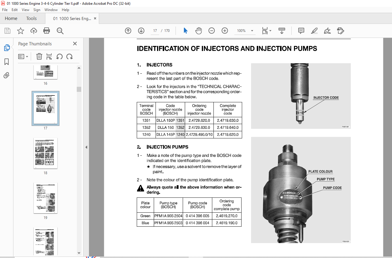
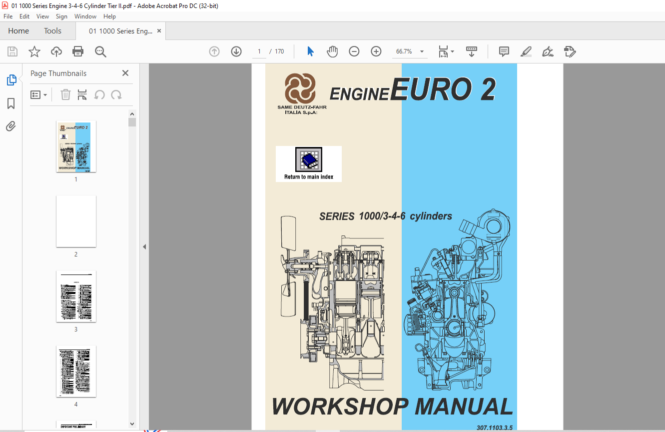
TABLE OF CONTENTS:
AGCO NA Engine EURO 2 Series 1000 3-4-6 Cylinders Workshop Manual – PDF DOWNLOAD
IMPORTANT PRELIMINARY
INFORMATION 1
HOW TO CONSULT THE MANUAL 3
HOW TO USE AND UPDATE THE MANUAL 4
LIFTING INSTRUCTIONS 5
STANDARD TIGHTENING TORQUES FOR NUTS
AND BOLTS 6
THREADLOCKERS, ADHESIVES, SEALANTS
AND LUBRICANTS 7
SPECIAL TOOLS 9
CONVERSION FACTORS 10
ENGINE TYPE IDENTIFICATION AND
SERIAL NUMBERS 11
IDENTIFICATION OF INJECTORS AND
INJECTION PUMPS 13
DETERMINING THE INJECTION
ADVANCE ANGLE 14
ENGINE DISASSEMBLY
1 PRELIMINARY REMOVAL OPERATIONS 15
2 REMOVAL OF THE COOLING AND INTAKE PIPES 18
3 REMOVAL OF THE CYLINDER HEADS 20
• 3 1 Dismantling the cylinder heads 28
• 3 2 Dismantling the rocker arm supports 29
4 REMOVAL AND TESTING OF THE
THERMOSTATS 30
• 4 1 REMOVAL 30
• 4 2 TESTING THE THERMOSTATS 31
5 REMOVAL OF THE COOLANT PUMP 32
• 5 1 3-AND 4-CYLINDERVERSIONS 32
• 5 2 6-CYLINDER VERSIONS 32
6 REMOVAL OF THE UNIT PUMPS, ACTUATOR AND
FUEL LIFT PUMP 33
7 OVERHAUL OF THE MECHANICAL GOVERNOR
DRIVE 38
• 7 1 DISASSEMBLY 38
• 7 2 ASSEMBLY 40
8 OVERHAUL OF THE MECHANICAL GOVERNOR
{STANDARD AND WITH L D A ) 44
• 8 1 DISASSEMBLY OF THE STANDARD
GOVERNOR 44
• • 8 1 1 Separation of the lower and
upper housings 44
• • 8 1 2 Assembly of the lower housing 49
• • 8 1 3 Adjusting the height of the lever
control bush 50
• • 8 1 5 Assembly of the upper housing 54
• • 8 1 6 Assembly of the governor housing 54
• 8 2 DISASSEMBLY OF THE GOVERNOR
WITH L D A VALVE 55
• • 8 2 1 Separating the upper and lower
housings 55
• • 8 2 2 Renewal of the membrane 56
• • 8 2 3 Completion of the disassembly 57
• • 8 2 4 Assembly of the governor with
L D A valve 59
• 8 3 BENCH ADJUSTMENT OF L D A VALVE 61
• • 8 3 1 Adjusting the length of the tie-rod 61
• • 8 3 2 Adjusting the spring load 61
• • 8 3 3 Adjusting the membrane travel 62
• 8 4 FINAL ADJUSTMENTS 62
• • 8 4 1 Adjusting the fuel flow rate 62
• • 8 4 2 Calibration for mechanical
governors 63
• • 8 4 3 Adjusting the maximum speed 64
• • 8 4 4 Hunting adjustment 64
• • 8 4 5 Adjusting the idle speed 65
• • 8 4 6 Sealing the governor 65
9 ADJUSTMENT OF THE ELECTRONIC
ACTUATOR 66
• 9 1 CALIBRATION OF ELECTRONIC
ACTUTAORS 67
10 REMOVAL OF THE INJECTION PUMP
CONTROL ROD 68
11 REMOVAL AND DISASSEMBLY OF THE HEAT
EXCHANGER
(For 4- and 6-cylinder versions) 69
12 DISMANTLING THE VALVE TIMING DRIVE 70
13 DISMANTLING THE CRANKSHAFT 73
• 13 1 REMOVAL OF THE HARMONIC BALANCER
(4-cylinder versions when fitted) 75
• 13 2 OVERHAUL OF THE HARMONIC BALANCER
(when fitted) 75
• • 13 2 1 Disassembly 75
• • 13 2 2 Assembly 76
• 13 3 REMOVAL OF THE CRANKSHAFT 76
• 13 4 DISMANTLING THE OIL PUMP 79
• • 13 4 1 3- and 4-cylinder versions 79
• • 13 4 2 6-cylinder version 80
30-i
14 REMOVAL OF THE PISTONS AND CYLINDER
LINERS 81
• 14 1 SEPARATING THE PISTON-CONNECTING
ROD ASSEMBLY 81
15 RENEWAL OF THE REAR CRANKSHAFT
OILSEAL 83
16 TESTS – TECHNICAL DATA AND DIMENSIONS 84
• 16 1 CYLINDER HEADS – VALVES –
ROCKER ASSEMBLIES 84
• • 16 1 1 Inspection and renewal of valve
guides 84
• • 16 1 2 Renewal of the valve guides 84
• • 16 1 3 Inspecting the valve seats 84
• • 16 1 4 Inspecting the valves 85
• • 16 1 5 Inspecting the valve springs 85
• • 16 1 6 Testing the valve seals 86
• • 16 1 7 Checking injector protrusion 86
• • 16 1 8 Renewal of the copper bushes 87
• • 16 1 9 Inspecting the rocker arms and
pivot posts 87
• • CYLINDER HEADS – VALVE GUIDES –
VALVE SEATS 88
• • VALVES – VALVE SPRINGS 89
• • ROCKER ARMS – ROCKER PIVOT
POSTS – TAPPETS 90
• 16 2 INJECTORS – INJECTION PUMPS 91
• • 16 2 1 Testing the injectors 91
• • INJECTOR TECHNICAL DATA –
NATURALLY ASPIRATED ENGINES 92
• CALIBRATION METHOD 93
• • INJECTOR TECHNICAL DATA –
TURBOCHARGED ENGINES 94
• • INJECTOR TECHNICAL DATA –
INTERCOOLER ENGINES 96
• 16 3 PISTONS – CONNECTING RODS 98
• • 16 3 1 Inspection of the pistons and piston
rings 98
• • 16 3 2 Inspecting the connecting rods
– gudgeon pins 99
• 16 4 INSPECTION OF THE BIG-END
CAP BOL TS100
• • PISTONS code 0 013 1456 0
(3-4-6 cylinder W engines) 101
• • PISTON RINGS 101
• • PISTONS code 0 012 8912 0
( 3- cylinder WT engines) 102
• • PISTON RINGS 102
• • PISTONS code 0 012 8913 0
( 4-6 cylinder WT engines) 103
• • PISTON RINGS 103
• • PISTONS code 0 012 8483 4/20
(4-6 cylinder WTI engines) 104
• • PISTON RINGS 104
• • CONNECTING RODS
(FOR PISTONS W-WT) 105
• • CONNECTING RODS
(FOR PISTONS WTl) 106
• 16 5 CRANKSHAFT 107
• • CRANKSHAFT (3-CYLINDER VERSION) 109
• • CRANKSHAFT (4-CYLINDER VERSION) 110
• • CRANKSHAFT (6-CYLINDER VERSION) 111
30-ii
CONTENTS
• 16 6 ENGINE BLOCK – CYLINDER LINERS 112
• • 16 6 1 Engine block 112
• • 16 6 2 Inspection of the cylinder liners 112
• • ENGINE BLOCK- CYLINDERS 114
• 16 7 CAMSHAFT 115
• • CAMSHAFT (13° STATIC ADVANCE) 116
• • CAMSHAFT (16° STATIC ADVANCE) 117
• 16 8TIMINGGEARS 118
• • 16 8 1 Removal of the gear shaft 118
• • TIMING GEARS 119
• 16 9 HARMONIC BALANCER
(For 4 cylinder engines only) 120
• • HARMONIC BALANCER 121
• 16 10 FLYWHEEL 122
ENGINE ASSEMBLY
17 FITTING THE PISTON COOLING NOZZLES 123
18 FITTING THE CYLINDER LINERS,
PISTONS AND CONNECTING RODS 124
19 FITTING THE CAMSHAFT-CRANKSHAFT AND
CONNECTING ROD BIG-ENDS 126
20 ASSEMBLY OF THE HARMONIC BALANCER
(For 4-cylinder engines only, only when fitted) 130
21 REFITTING THE OIL PUMP – SUMP PAN 131
• 21 13-AND4-CYLINDERVERSIONS 131
• 21 2 6-CYLINDER VERSION 131
• 21 3 ASSEMBLY OF THE ENGINE OIL SUMP 132
22 CALCULATING THE THICKNESSES OF THE
HEAD GASKETS AND REFITTING THE
CYLINDERHEADS 133
23 REFITTING THE CYLINDER HEADS 134
24 REFITTING THE INJECTION PUMP
CONTROL ROD 136
25 REFITTING THE MECHANICAL GOVERNOR DRIVE
AND THE ELECTRONIC GOVERNOR SUPPORT 137
26 ADJUSTMENT OF THE TIMING GEARS 138
27 VALVE TIMING 140
• 27 1 Checking the camshaft timing 141
28 TIMING THE INJECTION PUMPS 142
29 REFITTING THE ROCKER ASSEMBLIES 147
30 ADJUSTMENT OF VALVE CLEARANCES –
INJECTOR ASSEMBLY 148
• 30 1 Valve clearance adjustment 148
• 30 2 Injector assembly 148
31 FINAL ENGINE ASSEMBLY OPERATIONS 149
32 FINAL ENGINE ASSEMBLY – REAR END 161
33 ENGINE TESTS 164
• 33 1 Initial start-up and oil pressure check 164
• 33 2 Synchronizing the injection pumps 165
• • 33 2 1 Test 165
• • 33 2 2 Angular adjustment of the
injection pumps 165
More products