$35.95
Ammann ARP 95 Tandem Roller Workshop Manual 3031328 PDF
Ammann ARP 95 Tandem Roller Workshop Manual 3031328 – PDF DOWNLOAD
FILE DETAILS:
Ammann ARP 95 Tandem Roller Workshop Manual 3031328 – PDF DOWNLOAD
Language : English
Pages : 610
Downloadable : Yes
File Type : PDF
IMAGES PREVIEW OF THE MANUAL:

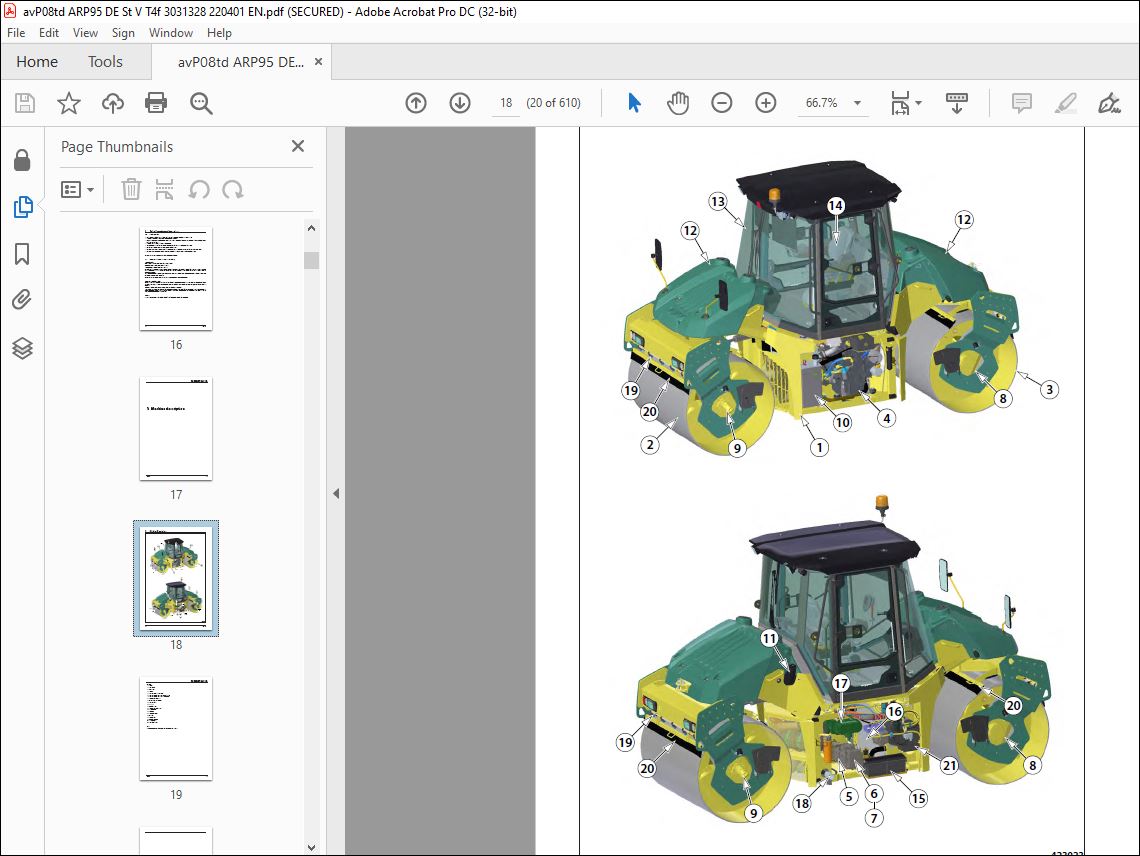
TABLE OF CONTENTS:
Ammann ARP 95 Tandem Roller Workshop Manual 3031328 – PDF DOWNLOAD
Contents 51 Introduction 91 1About this workshop manual 122 Safety measures and instructions 132 1Safety rules 142 2Environmental and hygiene principles 172 3Fire prevention 182 4Claim conditions and disclaimer of liability 183 Machine description 194 Specification manual 234 1Basic specification 244 2Machine dimension scheme 264 3Technical data 304 4Optional equipment 335 Media specification 355 1Engine oil 365 2Fuel 375 3Cooling liquid 375 4Hydraulic oil 385 5Gearbox oil 385 6Lube grease 385 7Glass washer fluid 385 8Drum cooling liquid 395 9Air Conditioning filling 395 10Vibratory oil 395 11Emulsion 395 12DEF (AdBlue) 395 13Media 406 Lubrication and Maintenance Chart 417 Ammann display 477 1Display control 488 Engine 598 1Description of the engine and basic components 618 2Technical data of the manufacturer 628 3Troubleshooting 638 4Engine removal 688 4 1Removal of the frame with the engine from the machine 698 4 2Removal of the engine from the frame 748 4 3Engine installation 809 Steering 819 1Description of basic elements 839 4Removal of the linear hydraulic motor of steering 859 4 1Replacement of the linear hydraulic motor of steering 859 4 2Replacement of the linear hydraulic motor of cab lifting 879 4 3Replacement of seals of the linear hydraulic motor 919 5Removal of the steering wheel 969 6Removal of the steering pump 999 6 1Installation of the steering pump 1029 7Removal of the hydraulic tank 1059 7 1Installation of the hydraulic tank 1099 8Removal of the oscillation plate bearings (003-051-1) 1129 8 1Installation of the oscillation plate bearings (003-051-1) 1179 9Steering block replacement 1269 10Setting the stops and setting the planeness 1329 10 1Adjustment of the stops 1329 10 2Adjustment of the planeness 13310 Travel 13510 1Description of the basic elements 13710 4Removal of the travel hydraulic motor 13810 4 1Installation of the travel hydraulic motor 15210 5Removal of the ACE travel hydraulic motor 16410 5 1Installation of the ACE travel hydraulic motor 17110 6Removal of the travel gearbox and hydraulic motor of ARP95 K 17810 6 1Installation of the travel gearbox and hydraulic motor of ARP95 K 18310 7Removal of the travel pump 18510 7 1Installation of the travel pump 19110 8Removal of the travel pump coupling 19410 8 1Installation of the travel pump coupling 19711 Vibration 19911 1Description of the basic elements 20111 4Removal of the vibration hydraulic motor 20311 4 1Installation of the vibration hydraulic motor 20711 5Removal of the vibration pump – rear drum 21011 5 1Installation of the vibration pump – rear drum 21411 6Removal of the vibration pump – front drum 21611 6 1Installation of the vibration pump – front drum 22011 7Removal of the drum from the machine 22311 7 1Installation of the drum in the machine 23411 7 2Installation of the damper plate – classic drum 24311 8Removal of vibrator bearings 24711 8 1Covers – removal of bearings 24711 8 2Vibrator – removal of inner rings 25911 9Installation of vibrator bearings 26311 9 1Covers – installation of bearings 26311 9 2Vibrator – installation of inner rings 26611 10Replacement of drum rubber-metals 26911 11Removal of the ACE vibrator 27311 11 1Remove of the ACE gearbox hydraulic motor 27311 11 2Removal of the vibrator from an ACE drum 27911 11 3Removal of inner bearing rings 28411 11 4Removal of bearings 29111 11 5Removal of the outer eccentric 29511 11 6Removal of the inner eccentric 29811 12Installation of the ACE vibrator 30011 12 1Installation of the inner eccentric 30011 12 2Installation of the outer eccentric 30511 12 3Installation of bearings 31011 12 4Installation of inner bearing rings 31511 12 5Installation of the vibrator in the drum 32011 12 6Mechanical setting of ACE system shaft and eccentric masses 32811 12 7Installation of the ACE gearbox hydraulic cylinder 33011 12 7 1 Linear sensor setting 33611 12 8Installation of the damper plate – ACE drum 33811 13Replacement of ACE drum rubber-metals 34211 14Adjustment of the vibration frequency 34611 15ACE PRO autocalibration 35011 16Removal of the bearing of the standard drum and ACE drum 35411 16 1Installation of the bearing of the standard drum and ACE drum 36012 Cooling 36712 1Description of basic components of the cooling hydraulics 36912 4Removal of the cooling hydraulic motor and propeller 37012 4 1Installation of the cooling hydraulic motor and propeller 37512 5Removal of the cooling pump 37812 5 1Installation of the cooling pump 38112 6Removal of the combined cooler 38313 Cab and platform 38913 1Replacement of the heater ball valve 39113 2Replacement of the heater 39513 3Replacement of the heater fan 39813 4Removal of the cab 40313 4 1Installation of the cab 41513 5Removal of the platform 42713 5 1Installation of the platform 43513 6Removal of the platform rubber-metals 44014 Fuel tank 44714 1Removal of the fuel tank 44914 1 1Installation of the fuel tank 45115 Sprinkling 45315 2Removal of the sprinkling pumps 45515 3Removal of the front water tank 45815 3 1Installation of the sprinkling pump 46315 3 2Installation of the front water tank 46415 4Removal of the rear water tank 46715 4 1Installation of the rear water tank 47116 Electrical installation 47316 2Measurement technique 47516 3Safety and instructions 47616 4Fitting of fuses 47716 5Removal of the seat switch 47816 6Removal of the travel lever and switches 48216 7Adjustment of the induction sensor 48616 8Batteries 48916 9Alternator 49116 9 1Removal of the alternator 49417 Troubleshooting 49717 1Machine error codes 49817 2Engine error codes 50118 Appendices 53718 1Measuring points 53918 1 1Conditions to measure the refilling pressure 54218 1 2Conditions to measure the cutter pressure 54318 1 3Conditions to measure the pressure in the steering circuit 54418 1 4Conditions to measure the travel pressure 54518 1 5Conditions to measure the vibration pressure 54618 1 6Conditions to measure the pressure in the cooling circuit 54918 2Wiring diagram ARP 95 55018 3Wiring diagram ARP 95 ACE 55618 4Electric installations cable harnesses 55918 5Hydraulic system diagram ARP 95 59818 6Hydraulic system diagram ARP 95 C 60018 7Hydraulic system diagram ARP 95 ACE 60218 8Hydraulic system diagram ARP 95C ACE 60418 9Check the tightening of bolted connections 606
More products