$34.95
Ammann ARS 110 Single Drum Roller Workshop Manual - PDF
Ammann ARS 110 Single Drum Roller Deutz TCD3.6 L4 EU Stage IV / U.S. EPA Tier 4f & EU Stage V / U.S. EPA Tier 4f Workshop Manual – PDF DOWNLOAD
FILE DETAILS:
Ammann ARS 110 Single Drum Roller Deutz TCD3.6 L4 EU Stage IV / U.S. EPA Tier 4f & EU Stage V / U.S. EPA Tier 4f Workshop Manual – PDF DOWNLOAD
Language : English
Pages : 270
Downloadable : Yes
File Type : PDF
ARS 110 DE St IV / T4f Product Identification Number 3022138-
ARS 110 DE StV / T4f Product Identification Number 3024804-
IMAGES PREVIEW OF THE MANUAL:
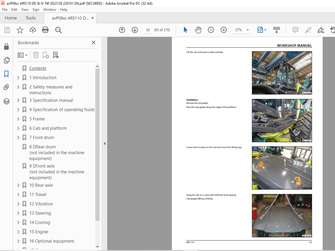
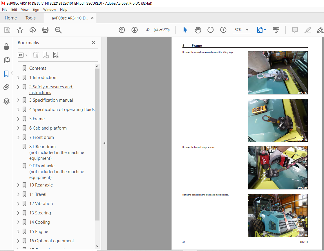
TABLE OF CONTENTS:
Ammann ARS 110 Single Drum Roller Deutz TCD3.6 L4 EU Stage IV / U.S. EPA Tier 4f & EU Stage V / U.S. EPA Tier 4f Workshop Manual – PDF DOWNLOAD
Contents 4
1 Introduction 9
1 1About this workshop manual 13
1 1 1Who is the workshop manual intended for 13
1 1 2Purpose 13
1 1 3Applicability of the workshop manual 13
1 1 4Validity of the workshop manual 13
2 Safety measures and instructions 15
2 1Safety rules 16
2 2Environmental and hygiene principles 19
2 3Fire prevention 20
2 4Claim conditions and disclaimer of liability 20
3 Specification manual 21
3 1Basic data 22
3 2Dimensioned drawing of the machine 24
3 3Technical data 26
3 3 1Technical data – ARS 110 EU Stage IV / U S EPA Tier 4f 26
3 3 2Technical data – ARS 110 EU Stage V / U S EPA Tier 4f 29
4 Specification of operating fluids 33
4 1Engine oil 34
4 2Fuel 35
4 3Coolant 35
4 4Hydraulic oil 36
4 5Gear oil 37
4 6DEF (AdBlue) 37
4 7Lubricating grease 37
4 8Screen washer fluid 37
4 9Drum coolant 37
4 10Air-conditioning filling 37
4 11Fluids 38
5 Frame 39
5 1Description of basic elements 41
5 3Electrical installation 42
5 3 1Fuses 42
5 3 2Relays 43
5 4Mechanical parts 43
5 4 1Removal of the bonnet 43
5 5Fuel tank 45
5 5 1Fuel level check 45
5 5 2Fuel replenishment 45
5 5 3Fuel drainage 46
5 5 4Fuel tank cleaning 47
5 6Hydraulic tank 48
5 6 1Hydraulic oil level check 48
5 6 2Hydraulic oil replenishment 49
5 6 3Hydraulic oil drainage 50
5 6 4Hydraulic oil filter replacement 51
5 6 5Ventilation filter replacement 52
6 Cab and platform 53
6 1Description of basic elements 55
6 3Electrical installation 56
6 3 6Control lever panel 56
6 3 7Other components 57
6 3 7 1Control unit of the machine A2 57
6 4Mechanical parts 57
6 4 1Setting of the control force of the travel control 57
6 5Cab 58
6 5 1Cab removal 58
6 7 Driver’s stand 73
6 7 4Display replacement 73
7 Front drum 75
7 1Description of basic elements 77
7 4Mechanical parts 78
7 4 1Replacement of vibration unit bearings 78
7 4 1 1Drum disassembly from the frame 78
7 4 1 3Drum assembly 82
8 Rear drum (not included in the machine equipment) 91
9 Front axle (not included in the machine equipment) 93
10 Rear axle 95
10 1Description of the basic elements 96
10 2Hydraulic parts 96
10 2 1Travel hydraulic motor 96
10 2 2Travel hydraulic motor replacement 97
10 4Mechanical parts 97
10 4 1Gearbox 97
11 Travel 99
11 1Description of the basic elements 100
11 2Hydraulic parts 101
11 2 1Travel pump replacement 101
11 2 2Flushing block replacement 104
11 2 3Travel hydraulic motor replacement 105
11 2 3 1Drum hydraulic motor replacement 105
11 2 3 2Rear axle travel hydraulic motor replacement 107
11 2 4Replacement of the brake block 109
11 3Electrical installation 111
11 3 1Travel pump coils replacement 111
11 3 2Travel hydraulic motor coils replacement 112
11 4Mechanical parts 115
11 4 1BOVEX coupling replacement 115
12 Vibration 119
12 1Description of basic elements 120
12 3Electrical installation 121
12 3 1Vibration pump coil replacement 121
13 Steering 123
13 1Description of basic elements 124
13 2Hydraulic parts 125
13 2 1Linear hydraulic motor replacement 125
13 2 2Replacement of the gasket of the linear hydraulic motor for steering 126
13 2 3Replacement of the steering hydraulic unit 130
13 2 4Steering pump 136
13 3Electrical installation 136
13 3 1Display replacement 136
13 3 2Travel control replacement 137
13 4Mechanical parts 138
13 4 2Steering wheel removal 138
14 Cooling 139
14 1Description of basic elements 140
14 2Hydraulic parts 140
14 2 1Cooling hydraulic motor replacement 141
14 3Electrical installation 151
14 3 1Replacement of the electromagnet coil of the cooling hydraulic motor 151
14 4Mechanical parts 152
14 4 1Replacement of the cooling fan, cooling fan spacer 152
15 Engine 163
15 1Description of basic elements 164
15 2Hydraulic parts 169
15 2 1Steering pump replacement 169
15 3Electrical installation 170
15 3 1Batteries 170
15 3 2Alternator replacement 170
15 3 3Starter replacement 170
15 4Mechanical parts 171
16 Optional equipment 185
16 1Optional equipment list 186
17 General procedures 187
17General procedures 188
17 2Electrical installation 189
17 2 1Travel pump magnetic coil check 189
17 2 2Preparation for welding works 191
17 2 3Starting the battery by means of another battery (jumping) 191
17 2 4Charging the battery with a charger 192
17 2 5Long-term storage 192
17 2 6Battery replacement 192
17 4Calibration and setting 193
17 4 1Pump current calibration 193
17 4 1 1Required material 193
18 Troubleshooting 195
18 1SW error diagnostics 196
18 1 1Machine errors 196
18 1 2Errors due to safety functions 198
18 1 3Errors at the inputs 199
18 1 4Errors at the outputs 200
18 1 5ACE errors 201
18 1 6System errors 202
18 1 7Engine errors 203
18 2 3 Travel control check 228
18 2 14Travel control 228
18 2 14 1Travel control replacement 228
18 2 14 2Travel lever switch check and replacement 228
19 Appendices 229
19 1Hydraulic system 231
19 1 1Travel pump zero position adjustment 231
19 1 1 1Travel pump magnetic coil check 231
19 2Wiring diagram 232
19 3Hydraulic diagram – wheel lock 240
19 4Hydraulic diagram – complete ATC 242
19 5Harnesses 244
19 6Check of the screw connections for tightening 263
19 7List of spare parts specified in the publication 265
More products