$33.95
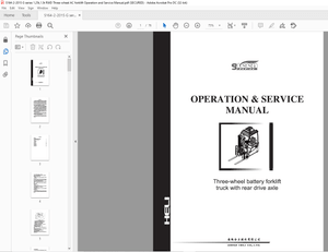
Ammann ARS 200 ARS 220 Single Drum Roller Operating Manual - PDF
Ammann ASC 220 Single Drum Roller Deutz EU Stage III/ U.S.EPA Tier 3 Operating Manual – PDF DOWNLOAD
ARS 200 St IIIA / T3 Product Identification Number 3043017 –
ARS 220 St IIIA / T3 Product Identification Number 2522001 –
FILE DETAILS:
Ammann ASC 220 Single Drum Roller Deutz EU Stage III/ U.S.EPA Tier 3 Operating Manual – PDF DOWNLOAD
Language : English
Pages :232
Downloadable : Yes
File Type : PDF
IMAGES PREVIEW OF THE MANUAL:
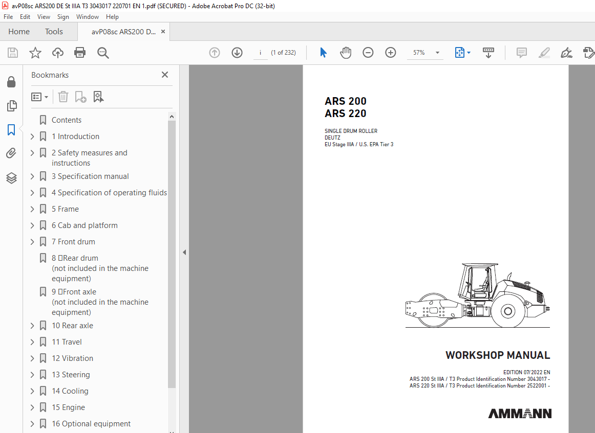
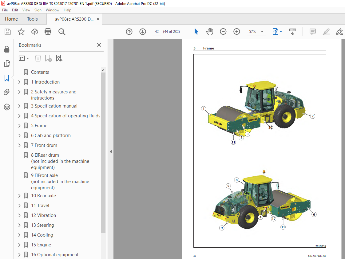
TABLE OF CONTENTS:
Ammann ASC 220 Single Drum Roller Deutz EU Stage III/ U.S.EPA Tier 3 Operating Manual – PDF DOWNLOAD
Contents 4
1 Introduction 9
1 1About this workshop manual 13
1 1 1Who is the workshop manual intended for 13
1 1 2Purpose 13
1 1 3Applicability of the workshop manual 13
1 1 4Validity of the workshop manual 13
2 Safety measures and instructions 15
2 1Safety rules 16
2 2Environmental and hygiene principles 19
2 3Fire prevention 20
2 4Claim conditions and disclaimer of liability 20
3 Specification manual 21
3 1Basic data 22
3 2Dimensioned drawing of the machine 24
3 3Technical data 28
3 3 1Technical data – ARS 200 28
3 3 2Technical data – ARS 220 32
4 Specification of operating fluids 37
4 1Engine oil 38
4 2Fuel 39
4 3Coolant 39
4 4Hydraulic oil 40
4 5Gear oil 40
4 6DEF (AdBlue) 41
4 7Lubricating grease 41
4 8Drum coolant 41
4 9Windscreen washer fluid 41
4 10Air-conditioning fluids 41
4 11Vibrator oil 41
4 11Media 42
5 Frame 43
5 1Description of basic elements 45
5 3Electrical installation 46
5 3 1Description 46
5 4Mechanical parts 48
5 5Fuel tank 50
5 5 1Fuel level check 50
5 5 2Fuel replenishment 50
5 5 3Fuel drainage 51
5 5 4Fuel tank cleaning 52
5 6Hydraulic tank 53
5 6 1Hydraulic oil level check 53
5 6 2Hydraulic oil replenishment 54
5 6 3Hydraulic oil drainage 55
5 6 4Hydraulic oil filter replacement 56
5 6 5Ventilation filter replacement 57
6 Cab and platform 59
6 1Description of basic elements 61
6 3Electrical installation 62
6 3 1Fuse box 62
6 3 2Output layout on the steering pillar 63
6 3 6Control lever panel 64
6 3 7Other components 65
6 3 7 1Control unit of the machine A2 65
6 4Mechanical parts 66
6 4 1Setting of the control force of the travel control 73
6 5Cab 74
6 5 1Cab removal 74
6 5 2Cab installation 79
6 7 Driver’s stand 84
6 7 4Display replacement 84
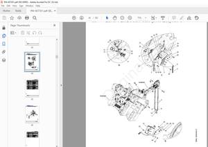
7 Front drum 85
7 1Description of basic elements 87
7 2Hydraulic parts 88
7 4Mechanical parts 90
7 4 1Replacement of vibration unit bearings 90
7 4 1 1Drum removal 90
7 4 1 3Drum assembly 101
8 Rear drum (not included in the machine equipment) 105
9 Front axle (not included in the machine equipment) 107
10 Rear axle 109
10 1Description of the basic elements 110
10 2Hydraulic parts 110
10 2 1Travel hydraulic motor 110
10 2 2Travel hydraulic motor replacement 111
10 4Mechanical parts 113
10 4 1Gearbox 113
11 Travel 115
11 1Description of the basic elements 116
11 2Hydraulic parts 117
11 2 1Travel pump replacement 120
11 2 3Travel hydraulic motor replacement 123
11 2 3 1Drum hydraulic motor replacement 123
11 2 3 2Rear axle travel hydraulic motor replacement 125
11 3Electrical installation 127
11 3 1Travel pump coils replacement 127
11 3 2Travel hydraulic motor coils replacement 127
11 4Mechanical parts 128
11 4 1BOVEX coupling replacement 128
12 Vibration 131
12 1Description of basic elements 132
13 Steering 133
13 1Description of basic elements 134
13 2Hydraulic parts 135
13 2 1Linear hydraulic motor replacement 135
13 2 2Replacement of the gasket of the linear hydraulic motor for steering 136
13 2 4Steering pump 140
13 3Electrical installation 140
13 3 1Display replacement 140
13 3 2Travel control replacement 141
13 4Mechanical parts 142
13 4 2Steering wheel removal 142
14 Cooling 143
14 1Description of basic elements 144
14 2Hydraulic parts 144
14 2 1Cooling hydraulic motor replacement 145
14 3Electrical installation 148
14 3 1Replacement of the electromagnet coil of the cooling hydraulic motor 148
14 4Mechanical parts 149
14 4 1Replacement of the cooling fan, cooling fan spacer 149
15 Engine 153
15 1Description of basic elements 154
15 2Hydraulic parts 158
15 2 1Steering pump replacement 158
15 3Electrical installation 159
15 3 1Batteries 159
15 3 2Alternator replacement 159
15 3 3Starter replacement 159
15 4Mechanical parts 160
16 Optional equipment 177
16 1Optional equipment list 178
17 General procedures 179
17General procedures 180
17 2Electrical installation 181
17 2 1Travel pump magnetic coil check 181
17 2 2Preparation for welding works 183
17 2 3Starting the battery by means of another battery (jumping) 183
17 2 4Charging the battery with a charger 184
17 2 5Long-term storage 184
17 2 6Battery replacement 184
17 4Calibration and setting 185
17 4 1Pump current calibration 185
17 4 1 1Required material 185
18 Troubleshooting 187
18 1SW error diagnostics 188
18 1 1Error codes 188
18 1 3Travel control check 188
18 2 14Travel control 188
18 2 14 1Travel control replacement 188
18 2 14 2Travel lever switch check and replacement 188
19 Appendices 189
19 1Hydraulic system 191
19 1 1Travel pump zero position adjustment 191
19 1 1 1Travel pump magnetic coil check 191
19 2Wiring diagram 192
19 3Hydraulic system diagram – RTM 200
19 5Harnesses 202
19 6Check of the screw connections for tightening 225
19 7List of spare parts specified in the publication 227
More products