$34.95
Ammann ARS 70 Single Drum Roller Workshop Manual 3001289 PDF
Ammann ARS 70 Single Drum Roller Kubota V3307-CR-TE5 EU Stage V / U.S. EPA Tier 4f Workshop Manual SN 3001289 – PDF DOWNLOAD
FILE DETAILS:
Ammann ARS 70 Single Drum Roller Kubota V3307-CR-TE5 EU Stage V / U.S. EPA Tier 4f Workshop Manual SN 3001289 – PDF DOWNLOAD
Language : English
Pages : 260
Downloadable : Yes
File Type : PDF
IMAGES PREVIEW OF THE MANUAL:
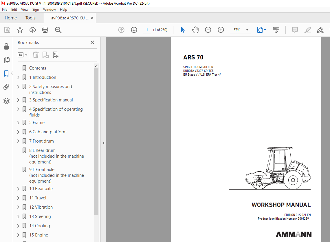

TABLE OF CONTENTS:
Ammann ARS 70 Single Drum Roller Kubota V3307-CR-TE5 EU Stage V / U.S. EPA Tier 4f Workshop Manual SN 3001289 – PDF DOWNLOAD
Contents 4
1 Introduction 9
1 1About this workshop manual 13
1 1 1Who is the workshop manual intended for 13
1 1 2Purpose 13
1 1 3Applicability of the workshop manual 13
1 1 4Validity of the workshop manual 13
2 Safety measures and instructions 15
2 1Safety rules 16
2 2Environmental and hygiene principles 19
2 3Fire prevention 20
2 4Claim conditions and disclaimer of liability 20
3 Specification manual 21
3 1Basic data 22
3 2Dimensioned drawing of the machine 24
3 3Technical data 26
4 Specification of operating fluids 29
4 1Engine oil 30
4 2Fuel 31
4 3Coolant 31
4 4Hydraulic oil 32
4 5Gearbox oil 32
4 6Lubricating grease 33
4 7Windshield washer liquid 33
4 8Air-conditioning filling 33
4 9Fills 34
5 Frame 35
5 1Description of basic elements 37
5 3Electrical installation 38
5 3 1Fuses 38
5 4Mechanical parts 40
15 4Mechanical parts 42
5 5Fuel tank 45
5 5 1Fuel level check 45
5 5 2Fuel replenishment 45
5 5 3Fuel drainage 46
5 5 4Fuel tank cleaning 47
5 6Hydraulic tank 48
5 6 1Hydraulic oil level check 48
5 6 2Hydraulic oil replenishment 49
5 6 3Hydraulic oil drainage 50
5 6 4Hydraulic oil filter replacement 51
6 Cab and platform 53
6 1Description of basic elements 55
6 3Electrical installation 55
6 3 2Output layout on the steering column 56
6 3 6Control lever panel 57
6 3 7Other components 57
6 3 7 1Control unit of the machine A2 57
6 4Mechanical parts 58
6 4 1Setting of the control force of the travel control 63
6 5Cab 64
6 5 1Cab removal 64
6 5 2Cab installation 69
6 7 Driver’s stand 72
6 7 4Display replacement 72
7 Front drum 73
7 1Description of basic elements 75
7 2Hydraulic parts 76
7 4Mechanical parts 77
7 4 1Replacement of vibration unit bearings 77
7 4 1 1Drum disassembly from the frame 77
7 4 1 2Disassembly of bearings of the vibration unit 83
7 4 1 3Assembly of bearings of the vibration unit 87
7 4 1 4Drum removal 92
8 Rear drum (not included in the machine equipment) 97
9 Front axle (not included in the machine equipment) 99
10 Rear axle 101
10 1Description of the basic elements 102
10 2Hydraulic parts 102
10 2 1Travel hydraulic motor 102
10 2 2Travel hydraulic motor replacement 103
10 4Mechanical parts 103
10 4 1Gearbox 103
10 4 2Wheels 104
10 4 3Wheel disassembly 104
11 Travel 105
11 1Description of basic elements 106
11 2Hydraulic parts 107
11 2 1Travel pump replacement 110
11 2 2Flushing block replacement 113
11 2 3Travel hydraulic motor replacement 114
11 2 3 1Drum travel hydraulic motor replacement 114
11 2 3 2Rear axle travel hydraulic motor replacement 117
11 2 4Brake block replacement 121
11 3Electrical installation 124
11 3 1Travel pump coils replacement 124
11 3 2Travel hydraulic motor coils replacement 124
11 4Mechanical parts 124
11 4 1BOVEX coupling replacement 124
12 Vibration 125
12 1Description of basic elements 126
13 Steering 127
13 1Description of basic elements 128
13 2Hydraulic parts 130
13 2 1Linear hydraulic motor replacement 130
13 2 2Steering linear hydraulic motor seal replacement 133
13 2 3Steering hydraulic unit replacement 137
13 2 3 1Disassembly of the hydraulic unit of the steering unit 137
13 2 3 2Assembly of the hydraulic unit of the steering unit 140
13 2 4Steering pump 143
13 3Electrical installation 143
13 3 1Display replacement 143
13 3 2Travel control replacement 144
13 4Mechanical parts 146
13 4 2Steering wheel removal 146
14 Cooling 147
14 1Description of basic elements 148
14 2Hydraulic parts 148
14 2 1Cooling hydraulic motor replacement 149
14 3Electrical installation 153
14 3 1Replacement of the electromagnet coil of the cooling hydraulic motor 153
14 4Mechanical parts 154
14 4 1Replacement of the cooling fan, cooling fan spacer 154
15 Engine 157
15 1Description of basic elements 158
15 2Hydraulic parts 163
15 2 1Steering pump replacement 163
15 3Electrical installation 164
15 3 1Batteries 164
15 3 2Alternator replacement 164
15 3 3Starter replacement 164
15 4Mechanical parts 165
16 Optional equipment 195
16 1Optional equipment list 196
17 General procedures 197
17 2Electrical installation 198
17 2 1Travel pump magnetic coil check 198
17 2 2Preparation for welding works 199
17 2 3Starting the battery by means of another battery (jumping) 199
17 2 4Charging the battery with a charger 200
17 2 5Long-term storage 200
17 2 6Battery replacement 200
17 4Calibration and setting 201
17 4 1Pump current calibration 201
17 4 1 1Required material 201
18 Troubleshooting 203
18 1SW error diagnostics 204
18 1 1Error codes 204
18 1 1 1Machine errors 204
18 1 1 2Errors due to safety functions 206
18 1 1 3Errors at the inputs 207
18 1 1 4Errors at the outputs 208
18 1 1 5ACE errors 210
18 1 1 6System errors 211
18 1 1 7Engine errors 212
18 1 3Travel control check 216
18 2 14Travel control 216
18 2 14 1Travel control replacement 216
18 2 14 2Travel lever switch check and replacement 216
19 Appendices 217
19 1Hydraulic system 219
19 1 1Travel pump zero position adjustment 219
19 1 1 1Travel pump magnetic coil check 219
19 2Wiring diagram 220
19 3Hydraulic diagram – wheel lock 228
19 4Hydraulic diagram – ATC inter-axle lock 230
19 5Harnesses 232
19 6Check of the screw connections for tightening 253
19 7List of spare parts specified in the publication 255
More products