Starting from:
$33.95
Ammann ARX 36-2 ARX 40-2 ARX 45-2 Tandem Roller Workshop Manual PDF
Ammann ARX 36-2 ARX 40-2 ARX 45-2 Tandem Roller Kubota V2403-M-E3B EU Stage IIIA/.U.S.EPA Tier 4i Workshop Manual – PDF DOWNLOAD
ARX 36-2 KU St IIIA / T4i Product Identification Number 3000000
ARX 40-2 KU St IIIA / T4i Product Identification Number 3001683
ARX 45-2 KU St IIIA / T4i Product Identification Number 3001685
FILE DETAILS:
Ammann ARX 36-2 ARX 40-2 ARX 45-2 Tandem Roller Kubota V2403-M-E3B EU Stage IIIA/.U.S.EPA Tier 4i Workshop Manual – PDF DOWNLOAD
Language : English
Pages :336
Downloadable : Yes
File Type : PDF
IMAGES PREVIEW OF THE MANUAL:
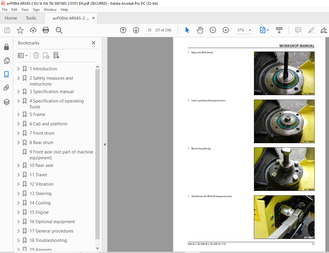

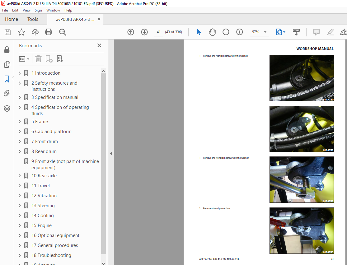
TABLE OF CONTENTS:
Ammann ARX 36-2 ARX 40-2 ARX 45-2 Tandem Roller Kubota V2403-M-E3B EU Stage IIIA/.U.S.EPA Tier 4i Workshop Manual – PDF DOWNLOAD
1	Introduction ...........................................................  9
	1.1	About this workshop manual........................................ 12
	1.1.1	Who is the workshop manual intended for......................... 12
	1.1.2	Purpose......................................................... 12
	1.1.3	Applicability of the workshop manual............................ 12
	1.1.4	Validity of the workshop manual................................. 12
2	Safety measures and instructions........................................ 13
	2.1	Safety rules...................................................... 14
	2.2	Environmental and hygiene principles.............................. 17
	2.3	Fire prevention................................................... 18
	2.4	Claim conditions and disclaimer of liability...................... 18
3	Specification manual.................................................... 19
	3.1	Basic data........................................................ 20
	3.2	Dimensioned drawing of the machine................................ 22
	3.3	Technical data.................................................... 24
4	Specification of operating fluids....................................... 27
	4.1.1	Engine oil ..................................................... 28
	4.1.2	Fuel............................................................ 29
	4.1.3	Coolant......................................................... 30
	4.1.4	Hydraulic oil................................................... 31
	4.1.5	Lubricating grease.............................................. 31
	4.1.6	Emulsion ....................................................... 31
	4.1.7	Fillings........................................................ 32
5	Frame................................................................... 33
	5.1	Description of basic elements..................................... 35
	5.4	Mechanical parts.................................................. 36
	5.4.1	Replacement of swinging support joint head...................... 36
	5.4.2	Replacement of swinging joint bearing........................... 37
	5.4.3	Lubrication of steering piston bearing.......................... 37
	5.4.4	Dashboard (screws).............................................. 38
	5.4.5	Gas pressure spring............................................. 38
	5.4.6	Disassembly/replacement of engine bonnet........................ 39
	5.4.7	Swinging support................................................ 41
	5.4.8	Replacement of joint head....................................... 41
	5.4.9	Swinging joint.................................................. 54
	5.4.10	Replacement of bearing......................................... 54
	5.5	Fuel tank......................................................... 64
	5.5.1	Fuel level check................................................ 64
	5.5.2	Fuel replenishment.............................................. 64
	5.5.3	Fuel drainage................................................... 65
	5.5.4	Cleaning the fuel tank.......................................... 65
	5.6	Hydraulic tank.................................................... 66
	5.6.1	Check of the hydraulic oil level................................ 66
	5.6.2	Hydraulic oil replenishment..................................... 66
	5.6.3	Hydraulic oil drainage.......................................... 67
	5.6.4	Hydraulic oil filter replacement................................ 68
	5.6.6	Ventilation filter replacement.................................. 69
	5.7	Water tank........................................................ 70
	5.7.1	Water tank removal.............................................. 70
	5.9	Sprinkling........................................................ 72
	5.9.2	Cleaning accessories............................................ 72
	5.9.3	Sprinkling device............................................... 72
	5.9.4	Sprinkling with shut-off valve.................................. 73
	5.9.5	Scraper......................................................... 73
	5.10	ROPS lifting and lowering........................................ 74
6	Cab and platform........................................................ 77
	6.1	Description of basic elements..................................... 79
	6.3	Electrical installation........................................... 80
	6.3.1	Steering column................................................. 80
	6.3.2	Output layout on the steering pillar............................ 80
	6.3.3	Relays and fuses in the engine compartment...................... 81
	6.3.4	Dashboard....................................................... 81
	6.3.5	Multifunctional display (A4).................................... 82
	6.3.6	Control lever panel............................................. 83
	6.3.7	Other components................................................ 83
	6.3.7.1	Control unit of the machine A3................................ 83
	6.4	Mechanical parts.................................................. 84
7	Front drum.............................................................. 85
	7.1	Description of basic elements..................................... 86
	7.2	Hydraulic parts................................................... 87
	7.2.1	Overview of hydraulic hoses..................................... 87
	7.3	Mechanical parts.................................................. 88
	7.3.1	Replacement of vibration unit bearings ......................... 88
	7.3.1.1	Drum removal ................................................. 88
	7.3.1.2	Mounting of the vibrator shaft................................106
	7.3.1.3	Removal of the vibrator shaft:................................114
	7.3.1.4	Installation of the roller drum...............................114
	7.3.1.5	Roller drum ballast...........................................134
8	Rear drum...............................................................137
	8.1	Description of basic elements.....................................138
	8.2	Hydraulic parts...................................................139
	8.2.1	Overview of hydraulic hoses.....................................139
	8.4	Mechanical parts..................................................140
	8.4.1	Replacement of vibration unit bearings..........................140
	8.4.1.1	Drum removal..................................................140
	8.4.1.2	Drum disassembly..............................................145
	8.4.1.3	Drum assembly.................................................153
9	Front axle (not part of machine equipment)..............................171
10	Rear axle..............................................................173
	10.1	Description of basic elements....................................174
	10.4	Mechanical parts.................................................175
	10.4.1	Replacement of travel motor at the pneumatic axle..............175
11	Travel.................................................................181
	11.1	Description of basic elements....................................182
	11.2	Hydraulic parts..................................................183
	11.2.1	Brake test.....................................................183
	11.2.1.1	Check of the parking brake...................................183
	11.2.1.2	Check of the emergency brake.................................184
	11.2.1.3	Check of the service brake...................................185
12	Vibration..............................................................187
	12.1	Description of basic elements....................................188
13	Steering...............................................................189
	13.1	Description of basic elements....................................190
14	Cooling................................................................191
	14.1	Description of basic elements....................................192
	14.2	Hydraulic parts..................................................193
	14.2.1	Hydraulic oil cooler cleaning..................................193
	14.4	Mechanical parts.................................................194
	14.4.1	Coolant and check of coolant level.............................194
	14.4.1.1	Coolant level check..........................................194
	14.4.1.2	Coolant replenishment........................................195
	14.4.1.3	Cooler cleaning..............................................195
15	Engine.................................................................197
	15.1	Description of basic elements....................................198
	15.1.1	Overview of engine compartment.................................198
	15.1.2	Kubota engine servicing........................................199
	15.3	Electrical installation..........................................200
	15.3.1	Steering pillar fuses..........................................200
	 15.4	Mechanical parts................................................201
	15.4.1	Fuel filter element............................................201
	15.4.2	Water separator filter element.................................201
	15.4.3	Engine oil.....................................................202
	15.4.3.1	Check of engine oil level....................................202
	15.4.3.2	Engine oil replenishment.....................................203
	15.4.3.3	Engine oil draining..........................................204
	15.4.3.4	Engine oil filter replacement................................205
	15.4.4	Inlet air filter...............................................207
	15.5	Hydraulic oil temperature sensor replacement.....................209
16	Optional equipment.....................................................215
	16.1	List of optional equipment.......................................216
17	General procedures.....................................................217
	17.2	Electrical installation..........................................218
	17.2.1	Travel pump magnetic coil check................................218
	17.2.2	Preparation for welding works..................................220
	17.2.3	Starting the battery by means of another battery (jumping) ....221
	17.2.4	Charging the battery with a charger............................222
	17.2.5	Long-term storage..............................................222
	17.2.6	Battery replacement............................................223
	17.2.7	Lamp replacement...............................................224
	17.2.7.1	Front lamp replacement.......................................224
	17.2.7.2	Rear lamp replacement........................................225
	17.4	Calibration and setting (calibration mode).......................226
	17.4.1	Calibration mode...............................................227
	17.4.2	Calibration of the minimum current of travel coils.............230
18	Troubleshooting........................................................233
	18.1	SW error diagnostics.............................................234
	18.1.1	Error codes....................................................234
	18.2	Pressure check...................................................240
	18.2.1	Pressure check and adjustment..................................240
	18.2.1.1	Vibration control valve......................................240
	18.2.2	Steering pressure setting......................................241
	18.2.3	Steering valve.................................................241
	18.2.4	Maximum pressure of vibration control valve....................242
	18.2.5	Travel pump check..............................................242
	18.2.5.1	Supply pressure check........................................242
	18.2.5.2	Travel pressure check........................................243
	18.2.7	Travel pump zero position adjustment...........................245
	18.2.7.1	Travel pump magnetic coil check..............................246
	18.2.8	Travel pump servo block check..................................248
	18.2.9	Edge cutter valve..............................................254
	18.2.10	Introduction..................................................258
	18.2.11	Brake valve magnetic coil check...............................259
	18.2.12	Quantity divider check........................................260
	18.2.13	Vibration control valve.......................................263
	18.2.13.1	Pressure valve..............................................263
	18.2.13.2	Magnetic coil...............................................267
	18.2.14	Travel controller.............................................268
	18.2.14.1	Travel controller replacement...............................268
	18.2.12.2	Switch check and replacement................................270
	18.2.15	Electronics replacement.......................................273
	18.2.16	Brake test....................................................277
	18.2.16.1	Check of the parking brake..................................277
	18.2.16.2	Check of the emergency brake................................277
	18.2.16.3	Check of the service brake..................................277
19	Annexes................................................................279
	19.1	Hydraulic system.................................................280
	19.1.1	Travel pump zero position adjustment...........................280
	19.1.1.1	Travel pump magnetic coil check..............................281
	19.2	Wiring diagram...................................................284
	19.3	Electric installations cable harnesses...........................291
	19.4	Hydraulic system diagram ARX 36-2, ARX 40-2, ARX 45-2............322
	19.5	Hydraulic system diagram ARX 36-2C, ARX 45-2C....................324
	19.6	Edge cutter hydraulic system diagram.............................326
	19.7	Workshop jigs....................................................328
	19.7.1	Tools..........................................................328
	19.7.2	Special tools for the drum.....................................328
	19.7.3	Special tool for measuring the speed and frequency.............331
	19.7.4	Special tool for magnetic coil check...........................331
	19.8	Miscellaneous....................................................331
1 file (21.3MB)

