Starting from:
$35.95
Ammann ARX 90 Tandem Roller Deutz Tier 3 Workshop Manual 4122043 PDF
Ammann ARX 90 Articulated Tandem Roller Deutz Tier 3 Workshop Manual 4122043 – PDF DOWNLOAD
FILE DETAILS:
Ammann ARX 90 Articulated Tandem Roller Deutz Tier 3 Workshop Manual 4122043 – PDF DOWNLOAD
Language : English
Pages : 384
Downloadable : Yes
File Type : PDF
IMAGES PREVIEW OF THE MANUAL:
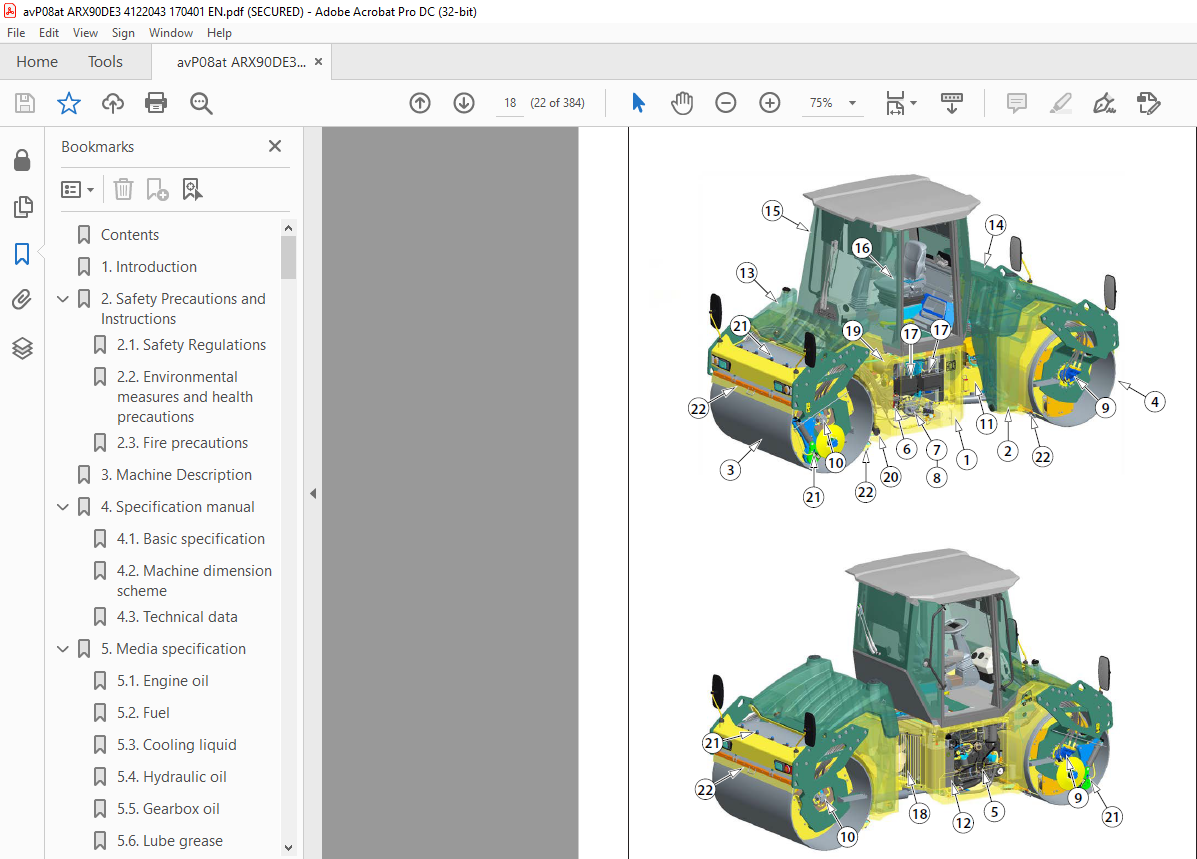
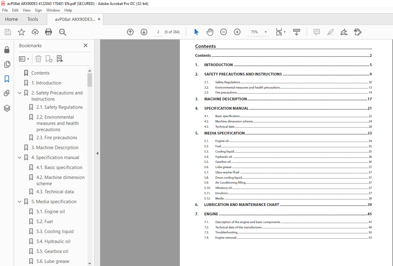
TABLE OF CONTENTS:
Ammann ARX 90 Articulated Tandem Roller Deutz Tier 3 Workshop Manual 4122043 – PDF DOWNLOAD
1. Introduction (pg. 61)
2. Safety Precautions and Instructions (pg. 92)
- 1. Safety Regulations (pg. 132)
- 2. Environmental Measures and Health Precautions (pg. 142)
- 3. Fire Precautions (pg. 172)
3. Machine Description (pg. 183)
4. Specification Manual (pg. 214)
- 1. Basic Specification (pg. 254)
- 2. Machine Dimension Scheme (pg. 264)
- 3. Technical Data (pg. 284)
5. Media Specification (pg. 325)
- 1. Engine Oil (pg. 375)
- 2. Fuel (pg. 385)
- 3. Cooling Liquid (pg. 395)
- 4. Hydraulic Oil (pg. 395)
- 5. Gearbox Oil (pg. 405)
- 6. Lube Grease (pg. 405)
- 7. Glass Washer Fluid (pg. 415)
- 8. Drum Cooling Liquid (pg. 415)
- 9. Air Conditioning Filling (pg. 415)
- 10. Vibratory Oil (pg. 415)
- 11. Emulsion (pg. 415)
- 12. Media (pg. 415)
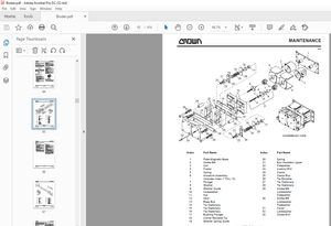
6. Lubrication and Maintenance Chart (pg. 426)
7. Engine (pg. 437)
- 1. Description of the Engine and Basic Components (pg. 497)
- 2. Technical Data of the Manufacturer (pg. 517)
- 3. Troubleshooting (pg. 537)
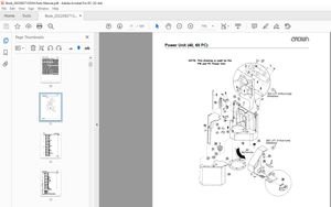
- 4. Engine Removal (pg. 547)
8. Steering (pg. 578)
- 1. Description of Basic Components (pg. 778)
- 2. Technical Data of the Manufacturer (pg. 798)
- 3. Steering Pump Removal (pg. 808)
- 4. Removal of the Linear Hydraulic Motor of the Steering and Crab (pg. 818)
- 4.1. Linear Hydraulic Motor – Crab (90/45-125) (pg. 868)
- 4.2. Linear Hydraulic Motor – Steering (90/45-420) (pg. 888)
- 4.3. Replacement of Sealings of the Linear Hydraulic Motor (pg. 908)
- 5. Steering Unit Removal (pg. 928)
- 6. Hydraulic Tank Removal (pg. 968)
- 7. Steering Wheel Removal (pg. 1008)
- 8. Steering Pillar Removal (pg. 1058)
- 9. Removal of the Steering Joint from the Machine (pg. 1088)
- 9.1. Removal of Bearings of the Steering Joint (pg. 1118)
- 9.2. Removal of Bearings of the Arm (pg. 1208)
9. Travel Hydraulic System (pg. 1289)
- 1. Description of Basic Components (pg. 1359)
- 2. Technical Data of the Manufacturer (pg. 1379)
- 3. Travel Hydraulic Motor Removal (pg. 1379)
- 4. Travel Gearbox Removal (pg. 1389)
- 5. Travel Pump Removal (pg. 1429)
10. Vibration System (pg. 14810)
- 1. Description of Basic Elements of Vibration Hydraulics (pg. 15510)
- 2. Technical Data of the Manufacturer (pg. 15710)
- 3. Removal of Vibration Hydraulic Motor (pg. 15810)
- 4. Removal of Vibration Pump on Front Drum (pg. 15910)
- 5. Removal of Vibration Hydraulic Pump from Rear Drum (pg. 16610)
- 6. Removal of Drum from Machine (pg. 17010)
- 7. Removal of Vibrator Bearings (pg. 17410)
- 8. Removal of Flange Bearings and Damper Plate (pg. 18410)
- 9. Removal of Rubber-Metals from Drum (pg. 19710)
11. Cooling System (pg. 20611)
- 1. Description of Basic Components of Cooling Hydraulics (pg. 21311)
- 2. Technical Data of the Manufacturer (pg. 21411)
- 3. Removal of Cooling Hydraulic Motor and Propeller (pg. 21511)
- 4. Cooling Pump Removal (pg. 21611)
- 5. Combined Cooler Disassembly (pg. 22211)
12. Cab and Platform (pg. 22712)
- 1. Ball Valve Heating Removal (pg. 23712)
- 2. Heating Removal (pg. 23912)
- 3. Heating Fan Removal (pg. 24212)
- 4. Cab Removal (pg. 24612)
- 5. Platform Removal (pg. 25012)
- 6. Removal of Rubber-Metals of the Platform (pg. 25612)
13. Fuel Tank Removal (pg. 26913)
14. Sprinkling System (pg. 27914)
- 1. Sprinkling Pump Removal (pg. 28714)
- 2. Water Tank Removal (pg. 28814)
15. Electrical Installation (pg. 29215)
- 1. Measurement Technique (pg. 29915)
- 2. Safety and Instruction (pg. 30115)
- 3. Fuse Positioning (pg. 30215)
- 4. Display Removal (pg. 30315)
- 5. Seat Switch Removal (pg. 30415)
- 6. Removal of the Travel Lever and Switches (pg. 30715)
- 7. Adjust Pulse Sensor (pg. 31115)
- 8. Accumulators (pg. 31615)
- 9. Alternator (pg. 31915)
- 10. Starter (pg. 32215)
16. Attachments (pg. 32516)
- 1. Wiring Diagram ARX 90, ARX 90 HF (pg. 32916)
- 2. Electric Installations Cable Harnesses (pg. 33016)
- 3. Hydraulic System Diagram ARX 90 (pg. 33916)
- 4. Hydraulic System Diagram ARX 90 HF (pg. 37016)
- 5. Hydraulic System Diagram ARX 90 K (pg. 37216)
- 6. Check the Tightening of Bolted Connections (pg. 37416)
- 7. List of Spare Parts Specified in the Publication (pg. 37816)
- 8. List of Groups from Spare Parts Catalog Used in the Publication (pg. 38016)
More products