Starting from:
$45.95
Ammann ARX 90 Tandem Roller Workshop Manual 3027368 PDF
Ammann ARX 90 Tandem Roller Deutz TCD3,6 L4 EU Stage IIIA / U.S. EPA Tier 3 Workshop Manual SN 3027368 – PDF DOWNLOAD
FILE DETAILS:
Ammann ARX 90 Tandem Roller Deutz TCD3,6 L4 EU Stage IIIA / U.S. EPA Tier 3 Workshop Manual SN 3027368 – PDF DOWNLOAD
Language : English
Pages : 384
Downloadable : Yes
File Type : PDF
IMAGES PREVIEW OF THE MANUAL:
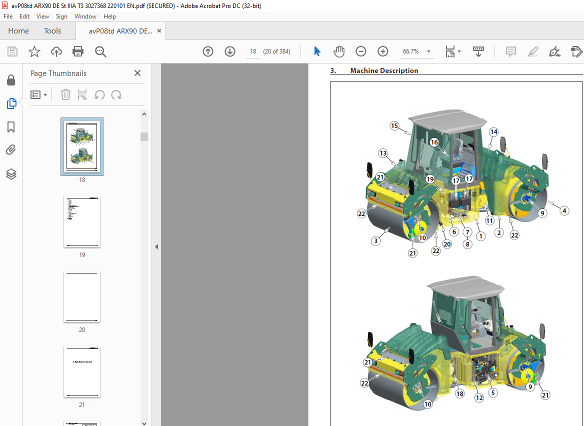
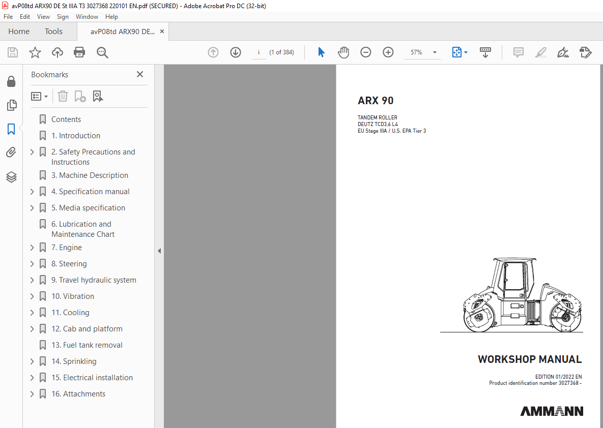
TABLE OF CONTENTS:
Ammann ARX 90 Tandem Roller Deutz TCD3,6 L4 EU Stage IIIA / U.S. EPA Tier 3 Workshop Manual SN 3027368 – PDF DOWNLOAD
1. Introduction (pg. 41)
2. Safety Precautions and Instructions (pg. 72)
- 1. Safety Regulations (pg. 112)
- 2. Environmental Measures and Health Precautions (pg. 122)
- 3. Fire Precautions (pg. 152)
3. Machine Description (pg. 163)
4. Specification Manual (pg. 194)
- 1. Basic Specification (pg. 234)
- 2. Machine Dimension Scheme (pg. 244)
- 3. Technical Data (pg. 264)
5. Media Specification (pg. 305)
- 1. Engine Oil (pg. 355)
- 2. Fuel (pg. 365)
- 3. Cooling Liquid (pg. 375)
- 4. Hydraulic Oil (pg. 375)
- 5. Gearbox Oil (pg. 385)
- 6. Lube Grease (pg. 385)
- 7. Glass Washer Fluid (pg. 395)
- 8. Drum Cooling Liquid (pg. 395)
- 9. Air Conditioning Filling (pg. 395)
- 10. Vibratory Oil (pg. 395)
- 11. Emulsion (pg. 395)
- 12. Media (pg. 395)
6. Lubrication and Maintenance Chart (pg. 406)
7. Engine (pg. 417)
- 1. Description of the Engine and Basic Components (pg. 477)
- 2. Technical Data of the Manufacturer (pg. 497)
- 3. Troubleshooting (pg. 517)
- 4. Engine Removal (pg. 527)
8. Steering (pg. 558)
- 1. Description of Basic Components (pg. 758)
- 2. Technical Data of the Manufacturer (pg. 778)
- 3. Steering Pump Removal (pg. 788)
- 4. Removal of the Linear Hydraulic Motor of the Steering and Crab (pg. 798)
- 4.1. Linear Hydraulic Motor – Crab (90/45-125) (pg. 848)
- 4.2. Linear Hydraulic Motor – Steering (90/45-420) (pg. 868)
- 4.3. Replacement of Sealings of the Linear Hydraulic Motor (pg. 888)
- 5. Steering Unit Removal (pg. 908)
- 6. Removal of the Hydraulic Tank (pg. 948)
- 7. Steering Wheel Removal (pg. 988)
- 8. Steering Pillar Removal (pg. 1038)
- 9. Removal of the Steering Joint from the Machine (pg. 1068)
- 9.1. Removal of Bearings of the Steering Joint (pg. 1098)
- 9.2. Removal of Bearings of the Arm (pg. 1188)
9. Travel Hydraulic System (pg. 1269)
- 1. Description of Basic Components (pg. 1339)
- 2. Technical Data of the Manufacturer (pg. 1359)
- 3. Travel Hydraulic Motor Removal (pg. 1359)
- 4. Travel Gearbox Removal (pg. 1369)
- 5. Travel Pump Removal (pg. 1409)
10. Vibration System (pg. 14610)
- 1. Description of Basic Elements of Vibration Hydraulics (pg. 15310)
- 2. Technical Data of the Manufacturer (pg. 15510)
- 3. Removal of Vibration Hydraulic Motor (pg. 15610)
- 4. Removal of Vibration Pump on Front Drum (pg. 15710)
- 5. Removal of Vibration Hydraulic Pump from Rear Drum (pg. 16410)
- 6. Removal of Drum from Machine (pg. 16810)
- 7. Removal of Vibrator Bearings (pg. 17210)
- 8. Removal of Flange Bearings and Damper Plate (pg. 18210)
- 9. Removal of Rubber-Metals from Drum (pg. 19510)
11. Cooling System (pg. 20411)
- 1. Description of Basic Components of Cooling Hydraulics (pg. 21111)
- 2. Technical Data of the Manufacturer (pg. 21211)
- 3. Removal of Cooling Hydraulic Motor and Propeller (pg. 21311)
- 4. Cooling Pump Removal (pg. 21411)
- 5. Combined Cooler Disassembly (pg. 22011)
12. Cab and Platform (pg. 22512)
- 1. Ball Valve Heating Removal (pg. 23512)
- 2. Heating Removal (pg. 23712)
- 3. Heating Fan Removal (pg. 24012)
- 4. Cab Removal (pg. 24412)
- 5. Platform Removal (pg. 24812)
- 6. Removal of Rubber-Metals of the Platform (pg. 25412)
13. Fuel Tank Removal (pg. 26713)
14. Sprinkling System (pg. 27714)
- 1. Sprinkling Pump Removal (pg. 28514)
- 2. Water Tank Removal (pg. 28614)
15. Electrical Installation (pg. 29015)
- 1. Measurement Technique (pg. 29715)
- 2. Safety and Instruction (pg. 29915)
- 3. Fuse Positioning (pg. 30015)
- 4. Display Removal (pg. 30115)
- 5. Seat Switch Removal (pg. 30215)
- 6. Removal of the Travel Lever and Switches (pg. 30515)
- 7. Adjust Pulse Sensor (pg. 30915)
- 8. Accumulators (pg. 31415)
- 9. Alternator (pg. 31715)
- 10. Starter (pg. 32015)
16. Attachments (pg. 32316)
- 1. Wiring Diagram (pg. 32716)
- 2. Electric Installations Cable Harnesses (pg. 32816)
- 3. Hydraulic System Diagram ARX 90 (pg. 33616)
- 4. Hydraulic System Diagram ARX 90 HF (pg. 36816)
- 5. Hydraulic System Diagram ARX 90 C (pg. 37016)
- 6. Check the Tightening of Bolted Connections (pg. 37416)
- 7. List of Spare Parts Specified in the Publication (pg. 37616)
- 8. List of Groups from Spare Parts Catalog Used in the Publication (pg. 37616)
- 9. Error Codes (pg. 37716)
More products