$35.95
Ammann ARX 90 Tandem Roller Workshop Manual 4172021 PDF
Ammann ARX 90 Tandem Roller Deutz TCD3,6 L4 EU Stage IV / US EPA Tier 4f Workshop Manual 4172021 – PDF DOWNLOAD
FILE DETAILS:
Ammann ARX 90 Tandem Roller Deutz TCD3,6 L4 EU Stage IV / US EPA Tier 4f Workshop Manual 4172021 – PDF DOWNLOAD
Language : English
Pages : 434
Downloadable : Yes
File Type : PDF
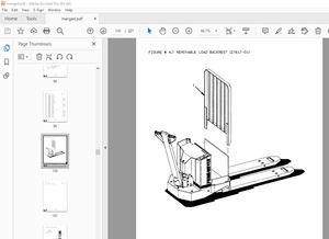
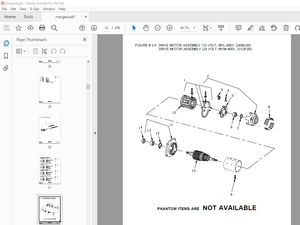
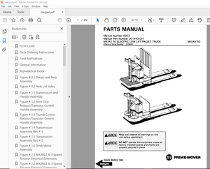
IMAGES PREVIEW OF THE MANUAL:


TABLE OF CONTENTS:
Ammann ARX 90 Tandem Roller Deutz TCD3,6 L4 EU Stage IV / US EPA Tier 4f Workshop Manual 4172021 – PDF DOWNLOAD
Contents 4
1 Introduction 7
2 Safety Precautions and Instructions 11
2 1 Safety Regulations 12
2 2 Environmental measures and health precautions 15
2 3 Fire precautions 16
3 Machine Description 17
4 Specification manual 21
4 1 Basic specification 22
4 2 Machine dimension scheme 24
4 3 Technical data 28
5 Media specification 31
5 1 Engine oil 32
5 2 Fuel 33
5 3 Cooling liquid 33
5 4 Hydraulic oil 34
5 5 Gearbox oil 34
5 6 DEF (AdBlue) 34
5 7 Lube grease 35
5 8 Glass washer fluid 35
5 9 Drum cooling liquid 35
5 10 Air Conditioning filling 35
5 11 Vibratory oil 35
5 12 Emulsion 35
5 13 Media 36
6 Lubrication and Maintenance Chart 37
7 Engine 43
7 1 Description of the engine and basic components 45
7 2 Technical data of the manufacturer 47
7 3 Troubleshooting 48
7 4 Engine removal 52
7 5 AdBlue tank removal 72
8 Steering 81
8 1 Description of basic components 83
8 2 Technical data of the manufacturer 84
8 3 Steering pump removal 85
8 4 Removal of the linear hydraulic motor of the steering and crab 90
8 4 1 Linear hydraulic motor – crab (90/45-125) 92
8 4 2 Linear hydraulic motor – steering (90/45-420) 94
8 4 3 Replacement of sealings of the linear hydraulic motor 96
8 5 Steering unit removal 100
8 6 Removal of the hydraulic tank 104
8 7 Steering wheel removal 109
8 8 Steering pillar removal 112
8 9 Removal of the steering joint from the machine 115
8 9 1 Removal of bearings of the steering joint 124
8 9 2 Removal of bearings of the arm 132
9 Travel 139
9 1 Description of basic components 141
9 2 Technical data of the manufacturer 141
9 3 Travel hydraulic motor removal 142
9 4 Travel gearbox removal 146
9 5 Travel pump removal 152
9 6 Travel hydraulic motors and gearboxes of ARX 90 K 159
9 6 1 Removal of the travel hydraulic motor and gearbox of ARX 90 K 163
9 6 2 Installation of the travel hydraulic motor and gearbox of ARX 90 K 163
10 Vibration 165
10 1 Description of basic elements of vibration hydraulics 167
10 2 Technical data of the manufacturer 168
10 3 Removal of vibration hydraulic motor 169
10 4 Removal of vibration pump on front drum 176
10 5 Removal of vibration hydraulic pump from rear drum 180
10 6 Removal of drum from machine 184
10 7 Removal of vibrator bearings 194
10 8 Removal of flange bearings and damper plate 207
10 9 Removal of rubber-metals from drum 216
11 Cooling 223
11 1 Description of basic components of the cooling hydraulics 224
11 2 Technical data of the manufacturer 225
11 3 Removal of the cooling hydraulic motor and propeller 226
11 4 Cooling pump removal 232
11 5 Combined cooler disassembly 237
12 Cab and platform 247
12 1 Ball valve heating removal 249
12 2 Heating removal 252
12 3 Heating fan removal 256
12 4 Cab removal 260
12 5 Platform removal 267
12 6 Removal of rubber-metals of the platform 281
13 Fuel tank removal 291
14 Sprinkling 299
14 1 Sprinkling pump removal 300
14 2 Water tank removal 304
15 Oscillation drum belt replacement 311
15 1Dismounting the belts 318
15 1Mounting the belts 330
16 Electrical installation 345
16 1 Measurement technique 347
16 2 Safety and instruction 348
16 3 Fuse positioning 349
16 4 Display removal 350
16 5 Seat switch removal 353
16 6 Removal of the travel lever and switches 357
16 7 Adjust pulse sensor 362
16 8 Accumulators 365
16 9 Alternator 368
16 10 Starter 371
17 Attachments 375
17 1 Wiring diagram 376
17 2 Wiring diagram of chip spreader 384
17 3 Electric installations cable harnesses 387
17 4 Hydraulic system diagram ARX 90 420
17 5 Hydraulic system diagram ARX 90 HF 422
17 6 Hydraulic system diagram ARX 90 K 424
17 7 Hydraulic diagram of chip spreader 426
17 8 Check the tightening of bolted connections 428
17 9 List of spare parts specified in the publication 430
17 10 List of groups from spare parts catalog used in the publication 431
More products