$35.95
Ammann AV 110 X Tandem Roller Workshop Manual 3002751 PDF
Ammann AV 110 X Tandem Roller Cummins QSB3.3-C99 EU Stage IIIA / U.S. EPA Tier 3 Workshop Manual SN 3002751 – PDF DOWNLOAD
FILE DETAILS:
Ammann AV 110 X Tandem Roller Cummins QSB3.3-C99 EU Stage IIIA / U.S. EPA Tier 3 Workshop Manual SN 3002751 – PDF DOWNLOAD
Language : English
Pages : 216
Downloadable : Yes
File Type : PDF
IMAGES PREVIEW OF THE MANUAL:
TABLE OF CONTENTS:
Ammann AV 110 X Tandem Roller Cummins QSB3.3-C99 EU Stage IIIA / U.S. EPA Tier 3 Workshop Manual SN 3002751 – PDF DOWNLOAD
Contents 4
1 Introduction 7
2 Safety Precautions and Instructions 11
2 1 Safety Regulations 12
2 2 Ecological measures & hygienic principles 16
2 3 Fire measures 17
3 Specification manual 19
3 1 Basic specification 20
3 2 Machine dimension scheme 22
3 3 Technical data 24
4 Media specification 27
4 1 Engine oil 28
4 2 Fuel 29
4 3 Cooling liquid 30
4 4 Hydraulic oil 30
4 5 Gearbox oil 31
4 6 Lube grease 31
4 7 Glass washer fluid 31
4 8 Drum cooling liquid 31
4 9 Air-conditioning filling 31
4 10 Media 32
5 Lubrication and Maintenance Chart 33
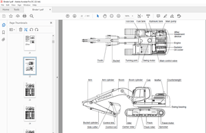
6 Drum 37
6 1 Disassembly of hydraulic motor for vibrations 39
6 2 How to remove hydraulic motor for travel 42
6 3 How to remove reducer 44
6 4 Front drum removal 45
6 5Replace drum’s metal rubbers 56
7 Knuckle Steering 59
7 1 How to remove steering joint 62
7 2 How to change steering joint bearings 66
7 3 Remove rotator’s bearings 70
8 Hydraulics 71
8 1 Remove cooling hydraulic motor 72
8 2 How to remove gear pump for steering 75
8 3 How to remove tandem pumps of vibration and travel 81
9 Removing hydromotors for steering and CRAB 89
9 1 Remove hydraulic cylinders for steering and CRAB 91
9 2 Remove sealants of hydraulic cylinders for steering and Crab 92
10 Bonnet Removal 97
11 Engine Removal 101
12 Removal of Coolers 119
13 Cabin 129
13 1 Heater Removal 131
13 2 Blower Removal 136
13 3 Wiper motor Removal 138
13 4 Seat Switch 141
13 5 Position sensor for neutral and parking brake 143
13 6 LH side control panel, backing horn sensor 143
13 7 Seat Platform 145
13 8 Power-Assisted Steering 149
13 9How to set up PowerView PV101 151
14 Wiring 153
14 1 Fuses 154
14 2 Accumulator 156
14 3 Alternator 157
14 4 Starter 159
14 5 Layout of wiring elements within the Machine 162
15 Annexes 165
15 1 Measuring the relief pressures of hydraulic circuit 166
15 2 Vibration frequency adjustment 170
15 3 Adjust pulse sensors 171
15 4 Wiring Diagram 174
15 5 Electric installations cable harnesses 181
15 6 Hydraulics Diagram 204
15 7 Check bolted connections are tightened 206
15 8 List of figures 208
15 9 Hand Signals 211
More products