$38
Bendi Landoll Forklift B30 & B40 ACDS DuraSteer ™ Parts Manual F-647-R1 – PDF DOWNLOAD
Bendi Landoll Forklift B30 & B40 ACDS DuraSteer ™ Parts Manual F-647-R1 – PDF DOWNLOAD
The Bendi Landoll Forklift B30 & B40 ACDS DuraSteer™ Parts Manual F-647-R1 – PDF DOWNLOAD provides detailed parts information essential for maintenance of B30 & B40 ACDS DuraSteer™ models, ensuring smooth operation.
FILE DETAILS:
Bendi Landoll Forklift B30 & B40 ACDS DuraSteer ™ Parts Manual F-647-R1 – PDF DOWNLOAD
Language : English
Pages :142
Downloadable : Yes
File Type : PDF
IMAGES PREVIEW OF THE MANUAL:
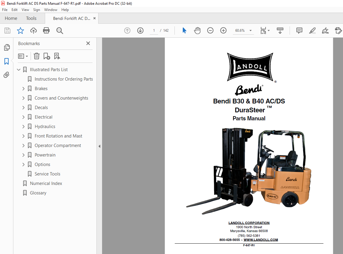
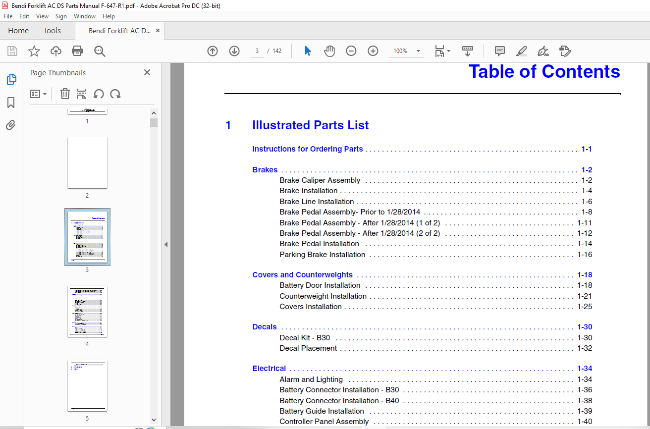
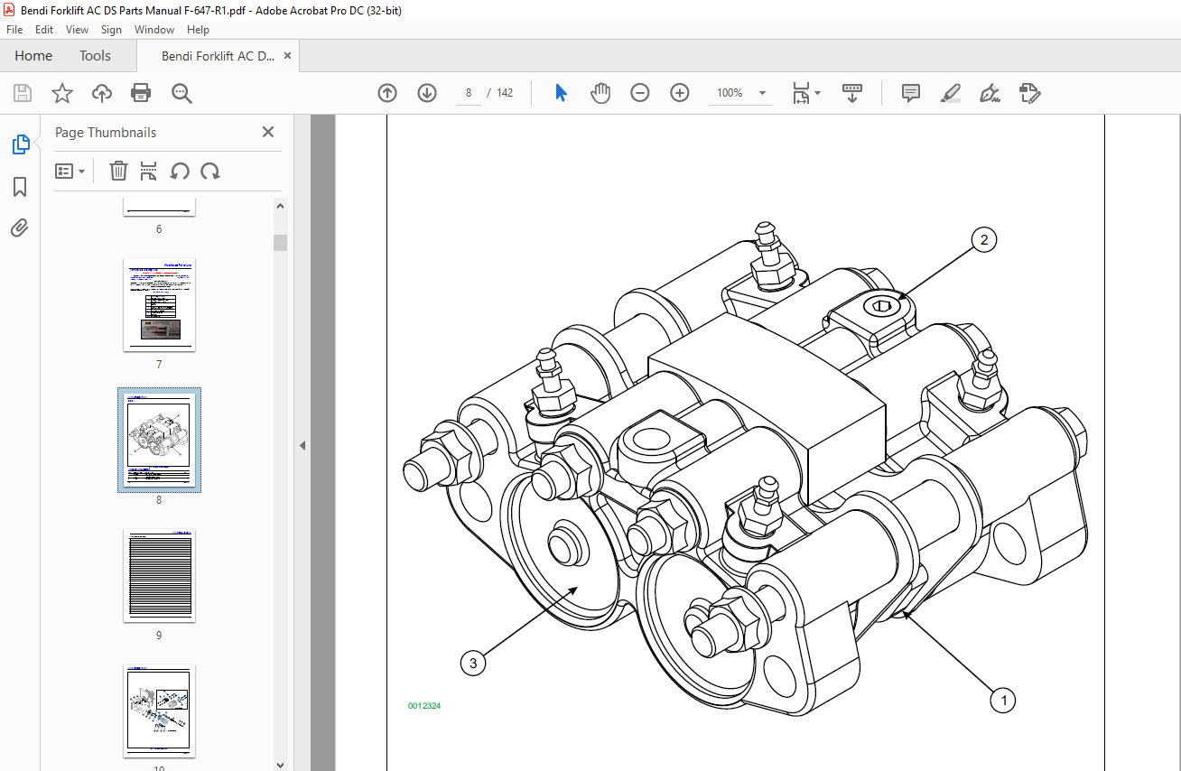
TABLE OF CONTENTS:
Bendi Landoll Forklift B30 & B40 ACDS DuraSteer ™ Parts Manual F-647-R1 – PDF DOWNLOAD
1 Illustrated Parts List
Instructions for Ordering Parts 1-1
Brakes 1-2
Brake Caliper Assembly 1-2
Brake Installation 1-4
Brake Line Installation 1-6
Brake Pedal Assembly- Prior to 1/28/2014 1-8
Brake Pedal Assembly – After 1/28/2014 (1 of 2) 1-11
Brake Pedal Assembly – After 1/28/2014 (2 of 2) 1-12
Brake Pedal Installation 1-14
Parking Brake Installation 1-16
Covers and Counterweights 1-18
Battery Door Installation 1-18
Counterweight Installation 1-21
Covers Installation 1-25
Decals 1-30
Decal Kit – B30 1-30
Decal Placement 1-32
Electrical 1-34
Alarm and Lighting 1-34
Battery Connector Installation – B30 1-36
Battery Connector Installation – B40 1-38
Battery Guide Installation 1-39
Controller Panel Assembly 1-40
Controller Installation 1-42
Drive Motor Assembly, AC Shaft – B30 to S/N 08552 1-43
Drive Motor Assembly, AC Shaft – B30 from S/N 08553 – 08932 1-44
Drive Motor Assembly, AC Shaft – B30 from S/N 08935 – Current 1-45
Drive Motor Assembly, AC Shaft – B40 to S/N 08403 1-46
Drive Motor Assembly, AC Shaft – B40 from S/N 08409 – 08861 1-47
Drive Motor Assembly, AC Shaft – B40 from S/N 08873 – Current 1-48
Fan Installation 1-49
Heavy Cable Diagram 1-50
ii F-647-R1
Lift Pump Motor Assembly to S/N 08212 (B30) & to S/N 08218 (B40) 1-52
Lift Pump Motor Assembly from S/N 08219/08222 – 09000/08861 (B30/B40) 1-53
Lift Pump Motor Assembly from S/N 09001/08873 – Current (B30/B40) 1-54
Light Wiring Diagram 1-56
Hydraulics 1-62
Hydraulic Connections, Frame 1-62
Hydraulic Control Valve Assembly 1-63
Hydraulic Diagram 1-64
Hydraulic Tank Components Installation 1-68
In-Tank Filter Assembly 1-70
Lift Pump and Motor Installation 1-71
Pressure Filter and Lines 1-72
Steering Column and Orbital Installation 1-74
Steering Control Valve Assembly 1-75
Tilt Cylinder 1-76
Tilt Cylinder, Limited Tilt 1-77
Front Rotation and Mast 1-78
Forks 1-78
Front Rotation Installation 1-79
Load Backrest 1-82
Load Wheel Assemblies 1-83
Mast Components Installation 1-85
Wheel and Axle Installation 1-88
Operator Compartment 1-90
Accelerator Pedal Assembly 1-90
Lift, Tilt, and Sideshift Controls 1-92
Overhead Guard Installation 1-94
Seat Assembly, Cloth 1-96
Seat Assembly, Vinyl 1-97
Seat Base Installation 1-98
Steering Column Assembly 1-100
Steering Column and Dash Display Assembly 1-102
Powertrain 1-104
Drive Motor and Gearbox Installation 1-104
Drive Wheel Components 1-105
Gearbox Assembly, 29:1 In-Line, Brevini 1-106
Options 1-107
Accessories 1-107
Battery Restraint Assembly 1-108
Fast Charge Battery Assembly – B30 1-110
Fast Charge Battery Assembly – B40 1-112
Roll Out Battery Tray Assembly – B40 1-114
Roll Out Battery Tray Assembly – B40 1-116
Roll Out Battery Tray Assembly – B30 1-118
F-647-R1 iii
Roll Out Battery Tray Assembly – B40 1-120
Service Tools 1-122
2 Numerical Index
3 Glossary
More products