$39
Bendi Landoll Forklift B40i5 Maintenance Manual F-809-R0 – PDF DOWNLOAD
Bendi Landoll Forklift B40i5 Maintenance Manual F-809-R0 – PDF DOWNLOAD
The Bendi Landoll Forklift B40i5 Maintenance Manual F-809-R0 – PDF DOWNLOAD offers detailed instructions for maintaining the B40i5 model, ensuring its optimal performance and longevity.
FILE DETAILS:
Bendi Landoll Forklift B40i5 Maintenance Manual F-809-R0 – PDF DOWNLOAD
Language : English
Pages : 188
Downloadable : Yes
File Type : PDF
IMAGES PREVIEW OF THE MANUAL:
DESCRIPTION:
Bendi Landoll Forklift B40i5 Maintenance Manual F-809-R0 – PDF DOWNLOAD
Introduction, Safety and Inspection
IntroductionThis manual is intended for the service technician who is seeking information on product maintenance and service replacement parts. It contains planned maintenance, troubleshooting tips, as well as information on repair which will help the technician resolve problems that may occur.Operating InstructionsThis manual does not contain operating instructions. Operating instructions are sent with each forklift. If the operators manual is missing on your Bendi B40i5 forklift, call Landoll Corporation to order a replacementService TrainingService Training is available for the forklift technician from Landoll Corporation. This includes operation, repair, maintenance, hydraulic system, electrical system and wire guidance. Contact Landoll Corporation at www.Landoll.com for more information.
TABLE OF CONTENTS:
Bendi Landoll Forklift B40i5 Maintenance Manual F-809-R0 – PDF DOWNLOAD
1 Introduction, Safety and Inspection
Before You Begin 1-1
Introduction 1-1
Operating Instructions 1-1
Service Training 1-1
Tools Needed 1-1
Replacement Parts 1-1
General Maintenance Instructions 1-2
For Your Safety 1-3
Battery Safety Rules: 1-3
Hydraulic System 1-3
Towing the Forklift 1-3
Towing Vehicle Requirements 1-4
Towing a Forklift in the Reverse Direction 1-4
Lifting and Blocking the Forklift 1-5
Prior to Tilt Cylinder Repair 1-5
Mast Removal 1-6
Cleaning & Inspecting the Forklift 1-6
Maintenance Introduction 1-7
Inspection Sheets 1-7
Lubrication Specifications 1-16
Torque Specifications 1-16
Fluid Capacities 1-16
2 Planned Maintenance
ii
Planned Maintenance Requirements 2-1
Tools or Equipment Required 2-1
Preparing for Inspection or Maintenance 2-2
Performance Testing 2-2
Completing Performance Testing 2-3
Daily Inspection 2-3
Fuel System Check 2-3
Power Steering Check 2-3
Checking the Battery 2-4
Check Hydraulic Functions 2-4
Check Driver’s Seat Switch 2-4
Check Hydraulic Oil Level 2-4
Check Engine Oil Level 2-5
Check Primary Lift Chain 2-6
Inspect Tires 2-6
Flat-Spotting 2-7
To Extend Tire Life 2-7
50 Hours Inspection 2-7
Hydraulic Pressure Filter Replacement 2-8
200 Hours Inspection 2-8
Check Nuts, Bolts, and Screws 2-8
Check Lift Operation 2-8
Drive Wheel Lug Nuts 2-9
Hydraulic System Maintenance 2-9
Side Shift Circuit Maintenance 2-10
Identification Plate and Safety Warnings 2-10
Check Tilt Cylinder Racking 2-10
Tilt Cylinder Racking and Tilt Degree Settings 2-10
Lubricating the Forklift 2-12
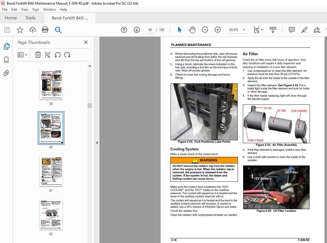
Cooling System 2-16
Air Filter 2-16
Change Engine Oil and Filter 2-17
Mast Maintenance 2-17
Load Roller Maintenance 2-18
Chain Maintenance 2-18
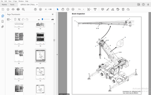
Fork Inspection 2-19
Lubricate Steer Wheel Knob 2-21
4500 Hours Inspection 2-21
Change Hydraulic Oil 2-21
3 Troubleshooting and Corrective Maintenance
Troubleshooting 3-1
ENGINE PROBLEMS 3-1
ELECTRICAL PROBLEMS 3-7
VISIBLE PROBLEMS 3-11
F-809-R0 iii
Corrective Maintenance 3-16
Lifting the Forklift 3-16
Floor Plate(s) Removal 3-16
Removing Forks 3-17
Repairing Forks 3-17
Load Testing Forks 3-17
Side Shifter 3-17
Mast Assembly Service 3-18
Removing the Mast From the Forklift 3-18
Wheel Bearings, Seals and Race 3-21
Front Axle Assembly 3-22
To Check Load Wheels 3-22
Removing the Front Axle 3-22
Articulation Bearing and Seal 3-23
Front Rotation Assembly 3-23
Removing the Steering Actuator 3-23
Stop Block 3-24
Steer (Front Rotation) Sensor 3-24
Auxiliary Pump – Steer and Lift Circuit 3-25
Replacing the Auxiliary Pump – Steer and Lift Circuit 3-25
Drive and Brake Pedals 3-26
Replacing the Drive (Accelerator) Pedal Assembly 3-26
Park Brake Pedal/Park Brake Assembly 3-26
Checking the Park Brake Efficiency 3-27
Steering Column and Console Assembly 3-27
Steering Wheel 3-27
Remove Right Side Cover 3-28
Display 3-28
Key Switch 3-28
Option Rocker (On/Off) Switches 3-29
Steering Column (Console) 3-30
Orbital Steer Unit 3-30
Load Sense Steering System 3-30
Steering Counterbalance Valve 3-31
Hydraulic Control Valve Assembly 3-31
General 3-31
Hydraulic Control Valve 3-33
Steer System Relief Valve 3-33
iv
Hydrostatic Pump 3-34
Charge Pressure Check 3-34
To Remove and Replace the Hydrostatic Pump 3-35
To Prime the Hydrostatic Pump 3-36
To Remove and Replace Hydrostatic Pump Manifold 3-36
Hydrostatic Drive Motor Assembly 3-36
To Remove Drive Wheels 3-36
Hydrostatic Drive Motors – Rear 3-37
To Replace Hydrostatic Drive Motor Assembly 3-38
Brake Service and Repair 3-38
Reassembly 3-40
Seat Assembly/Horn 3-48
Seat Switch 3-48
Horn and Direction Control 3-48
Engine Assembly 3-49
Engine 3-49
Fuel System 3-49
Overhead Guard/Lighting/Alarms 3-51
Back Up Alarms 3-51
4 Calibration and Programming
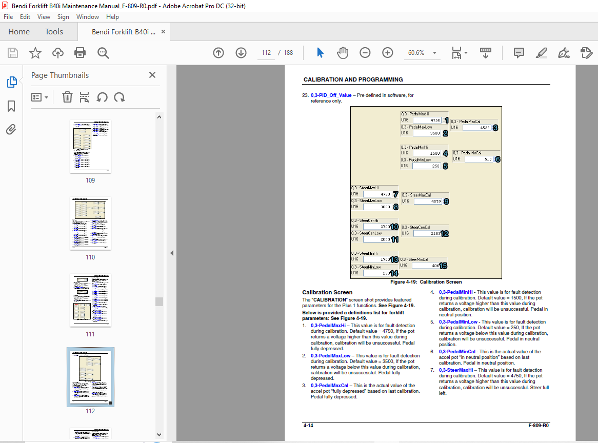
Vehicle Controller “Plus 1” Calibration and Programming 4-1
Getting Started Using Plus 1 Software 4-1
ECU Downloading and Type 4-3
Format 4-3
Log Functions 4-4
Dash Display Calibration and Operation 4-16
5 Engine with Fuel System
More products