$45
Bobcat 641 642 643 Loader Service Manual 6566135 (6-12) - PDF DOWNLOAD
Bobcat 641 642 643 Loader Service Manual 6566135 (6-12) - PDF DOWNLOAD
FILE DETAILS:
Bobcat 641 642 643 Loader Service Manual 6566135 (6-12) - PDF DOWNLOAD
Language : English
Pages : 386
Downloadable : Yes
File Type : PDF
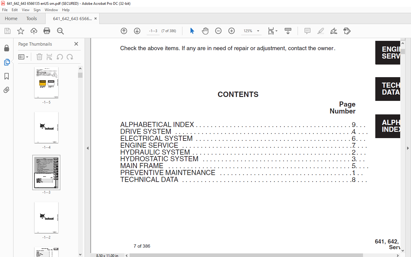
TABLE OF CONTENTS:
EXCERPT:
PREVENTIVE MAINTENANCE
Paragraph Page
Number Number
AUXILIARY CONTROL LOCKBOLT . . . . . . . . 1–15 1–20
BOB–TACH . . . . . . . 1–13 1–19
DRIVE BELTS . . . . . . 1–6 1–12
ELECTRICAL SYSTEM . . . . . . . . . 1–7 1–13
ENGINE COOLING SYSTEMS . . . . . . . . . . . . . 1–5 1–10
ENGINE SERVICE . . . . . . . . . . . . . 1–3 1–4
FINAL DRIVE . . . . . . . 1–9 1–17
FUEL SYSTEM . . . . . 1–4 1–8
HYDRAULIC/HYDROSTATIC SYSTEM . . . . . . 1–8 1–15
INTRODUCTION . . . . 1–1 1–1
LIFT ARM STOP . . . . . . . . . . . . . . 1–16 1–20
LUBRICATION OF THE BOBCAT LOADER . . . . . . . . . . . . 1–11 1–18
OPERATOR GUARD . . . . . . . . . . 1–12 1–19
PIVOT PINS . . . . . . . 1–14 1–20
SERVICE SCHEDULE . . . . . . . . . . 1–2 1–3
TIRE MAINTENANCE . . . . . . . . . 1–10 1–17
DESCRIPTION
To install new brake/puck assembly (Fig. 4–10):
13. Remove the brake block (Item 1) from the transmission cover (Item 2).
14. Remove the brake pucks (Item 3) and check them for wear and damage.
Replace the pucks and wear plates as needed. Check the cam pin for damage.
15. Install the wear plates (Item 4) and pucks into the brake block.
16. Put a new O–ring (Item 5) onto the cam pin and install the cam pin into the brake block.
17. Put a bead of silicone rubber sealant on the side of the brake block that the transmission cover fastens to.
18. Apply LOCTITE to the bolts used to fasten the transmission cover to the brake block.
19. Install the bolts and tighten the bolts 65–70 ft.–lbs. (88–95 Nm) torque.
20. Put the brake assembly and transmission cover over the brake discs (Fig. 4–11).
21. Align the brake discs so they are centered between the brake pucks.
22. Align the holes. Install the bolts and tighten 16–20 ft.–lbs. (22–27 Nm) torque.
23. Install the brake linkage (See Steps 4–11 under Brake Assembly).
NOTE: Remove the spacer from under the hydrostatic pump. Install the bolts into the rubber bushings while holding the pump up to prevent bushings from being pushed out.
4–2 FINAL DRIVE
The final drive does not have connector links, but if the chain is separated during maintenance use a press link for assembly.
4–2.1 Chain Replacement
The tools listed will be needed to do the following procedure:
MEL1045 Chain Breaker
MEL1037 Chain Link Tool Set
…
IMAGES PREVIEW OF THE MANUAL:
More products