$34
Bomag BC 601 RB BC 601 RS Sanitary landfill compactor Instruction For Repair Manual 00819144 PDF
Bomag BC 601 RB BC 601 RS Sanitary landfill compactor Instruction For Repair Manual 00819144 – PDF DOWNLOAD
FILE DETAILS:
Bomag BC 601 RB BC 601 RS Sanitary landfill compactor Instruction For Repair Manual 00819144 – PDF DOWNLOAD
Language : English
Pages : 458
Downloadable : Yes
File Type : PDF
Size: 34 MB
DESCRIPTION:
Bomag BC 601 RB BC 601 RS Sanitary landfill compactor Instruction For Repair Manual 00819144 – PDF DOWNLOAD
Foreword
These repair instructions contain necessary information on
• Training
• Trouble shooting
• Repair.
Notes regarding maintenance and care can be taken
from the operating and maintenance instructions.
These repair instructions are devided in assembly
groups and are therefore marked respectively:
01 General
02 Engine
03 Axles
04 Travel system
05 Wheels
06 Steering system, working hydraulics
07 Brake
08 Electrical system
09 Circuit diagrams
10 Optional equipment
- These instructions contain only such assembly groups as are needed on this particular machine. The repair section describes the removal resp. the dismantling of parts and assemblies.
- Installation must be performed in reverse order. Special notes for installation are given in frames within the text. Repair procedures for dismounted assembly groups are only described as far as they are reasonable with respect to working aids and spare parts supply and as far as a skilled mechanic is able to understand them.
IMAGES PREVIEW OF THE MANUAL:
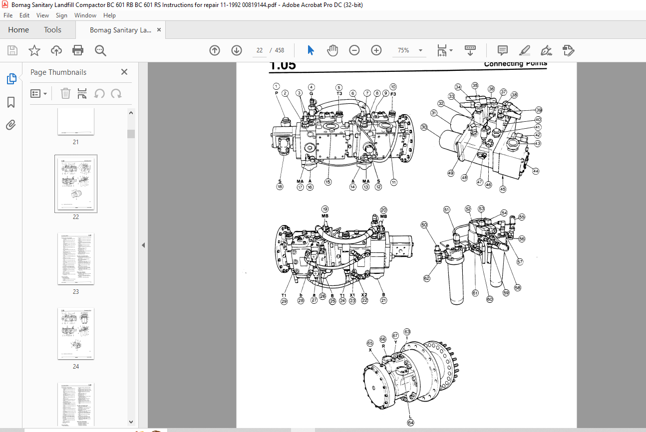
TABLE OF CONTENTS:
Bomag BC 601 RB BC 601 RS Sanitary landfill compactor Instruction For Repair Manual 00819144 – PDF DOWNLOAD
1 General
1 1 Safety Regulations 1-3
1 2 General Repair Instructions 1-5
1 3 Technical Data 1- 7
1 4 Torques 1-10
1 5 Connecting Points 1-11
1 6 Special Tools 1-18
2 Engine
2 1 Checking th~ Diesel Engine Speed 2-3
2 2 Checking the Peheating System 2-4
2 3 Removing and Installing the Engine 2-6
2 4 Preparing the Engine for Operation 2-17
2 5 Changing the Coupling 2-19
2 6 Removing and Installing the Distributor Gear 2-22
2 7 Repair Survey Distributor Gear 2-24
2 8 Repairing the Distributor Gear 2-26
4 Travel System
4 1 Pressure Tests in the Travel System 4-3
4 2 Checking High Pressure Relief Valves and the Pressure Cut-Of 4-4
4 3 Charge Pump High Pressure Test 4-6
4 4 Travel Pump High Pressure Test 4-7
4 5 Checking the Charge Pressure 4-8
4 6 Checking the Setting of the DA-Control Valve 4-9
4 7 Checking the Control Chamber Pressure 4-1 0
4 8 Checking the Swashing Angle Setting in the Travel Motors 4-11
4 9 Trouble Shooting Chart (Poclain and L&S Version) 4-16
4 10 Removing and Installing the Travel Pump 4-30
4 11 Overall view for sealing and chang the travel pumps I and I 4-32
4 12 General notes for repair 4-34
4 13 Changing the seallock nut 1 4-35
4 14 Sealing the drive shaft 2 for travel pumps I and II 4-36
4 15 Sealing1changing way valve and pressure cut-off valve 4-38
4 16 Sealing the hydraulic control for travel pumps I and II 4-39
4 17 Sealing/changing the DA-control valve 5 on travel pump I 4-41
4 18 Sealing/changing the high pressure relief valve 6 4-42
BC 601 RB/RS BOMAG 3
Foreword
4 19 Sealing/cleaning the charge pressure relief valve 7 4-43
4 20 Sealing the housing cover 8 4-44
4 21 Sealing the cover (9) on travel pump II 4-45
4 22 Sealing the timing screw 10 4-46
4 23 Sealing the bearing cage guiding 11 (Fig 1 ) 4-47
4 24 Cleaning the nozzles 12 (Fig 1 ) 4-48
4 25 Sealing the pump flange 13 (Fig 1 ) 4-49
4 26 Repair survey for travel pumps I and II 4-50
4 27 General notes for repair 4-52
4 28 Repairing the travel pumps I and II 4-53
4 29 Removing and Installing the Travel Motor (Poclain) 4-64
4 30 Repair survey for travel motor (Poclain) 4-67
4 31 General notes for repair 4- 70
4 32 Repairing the travel motor 4- 71
4 33 Repairing the brake in the travel motor 4- 76
4 34 Removing and Installing the Travel Motor with Final Drive 4- 78
4 35 Repair survey travel motor 4-82
4 36 Repair survey 4-82
4 37 General notes for repairs 4-83
4 38 Sealing the drive shaft 4-84
4 39 Sealing the end plate 4-87
4 40 Repairing the Brake in the Final Drive 4-91
4 41 Repairing the Final Drive 4-94
4 42 Removing and Installing the Charge Pump 4-100
4 43 Sealing the Charge Pump 4-101
4 44 Changing the Thermostat Valve 4-104
4 45 Filling the Hydraulic System and Taking it into Operation 4-105
4 46 Causing a Vacuum in the Hydraulic Oil Tank 4-108
5 Wheels
5 1 Welding the Shoe Segments 5-3
5 2 Changing the Wheel Tips 5-4
6 Steering/dozer blade hydraulics
6 1 Checking the Setting of the Steering/Dozer Blade Pump 6-3
6 2 Checking the Pump High Pressure 6-4
6 3 Checking the Dozer Blade Precontrol Pressure 6-5
6 4 Checking the Load Signal to the Steering/Dozer Blade Pump 6-6
4 BOMAG BC 601 RB/RS
Foreword
6 5 Checking the Steering Hydraulics and the Steering pressure 6- 7
6 6 Trouble Shooting Charts 6-8
6 7 Removing and Installing the Steering/Dozer Blade Pump 6-13
6 8 Repair survey steering I dozer blade pump 6-14
6 9 Repair Survey 6-14
6 1 O General Notes for Repairs 6-15
6 11 Sealing the drive shaft 6-16
6 12 Sealing/changing the Control Valve 6-18
6 13 Sealing the Connecting Plate 6-19
6 14 Repairing the Pump Drive 6-21
6 15 Removing and Installing the Control Valve Block 6-30
6 16 Repair Survey Control Valve 6-31
6 17 General Notes for Repairs 6-34
6 18 Sealing the Control Valve 6-35
6 19 Removing and Installing the Steering Cylinder 6-41
6 20 Repairing the Steering Cylinder 6-43
6 21 Removing and Installing the Dozer Blade Cylinder 6-46
6 22 Repairing the Dozer Blade Cylinder 6-47
6 23 Changing the Precontrol Valve 6-50
6 24 Dismounting and Installing the Dozer Blade 6-51
6 25 Removing and Installing Cross-Type Roller Bearing for Articulated Center Joint 6-53
6 26 Repairing the Oscillating Articulated Center Joint 6-59
6 27 Removing and Installing the Steering Valve 6-62
6 28 Repair survey steering valve 6-64
6 29 General notes for repairs 6-66
6 30 Repairing the steering valve 6-67
8 Electric system
8 1 Overall view of installation box 8-3
8 2 Description of the most important circuits 8-4
8 3 Relay board 8-13
8 4 Testing the relay board 8-18
8 5 Testing chart for relay board 8-20
8 6 Relay board for brake control 8-21
8 7 Testing the relay board for the brake control 8-25
8 8 Testing chart for brake control relay board 8-27
8 9 Monitoring module (A15) 8-28
BC 601 RB/RS BOMAG 5
Foreword
8 1 0 Testing the monitoring board (A 15) 8-34
8 1 1 Testing chart for monitoring board (A 15) 8-36
8 12 Control and regulation of heating system 8-38
8 13 Trouble shooting heating system 8-42
8 14 Testing chart for heating system control unit 8-43
8 15 Lubrication system control 8-44
8 16 Exemplary trouble shooting · 8-45
8 Electrical system from machine no and up
8 1 8 General view of the installation box 8-53
8 19 Description of the most important electric circuits 8-54
8 20 Time-invariant, clutch for air conditioning system (A21) 8-62
8 21 Control of the central lubrication system 8-63
8 22 Monitoring board (A15) 8-64
8 23 Testing the monitoring board (A 15) 8- 70
8 24 Testing chart for monitoring board (A15) 8-72
8 25 Circuit board for travel and preheating control (A22) 8- 7 4
8 26 Trouble shooting by using the circuit board A22 8-82
9 Circuit diagrams
9 1 Hydraulic diagram (L&S final drives) 9-3
9 2 Hydraulic diagram (Poclain motors) 9-7
9 3 Wiring diagram up to machine-no 9-11
9 4 Wiring diagram since machine-no 9-23
10 Optional equipment (air conditioning system)
10 1 Physical Basics 10-3
10 2 The Refrigerant Circuit 10-5
10 3 Description of Components 10-8
10 4 Technical Data 10-14
10 5 Safety instructions for the air conditioning system 10-16
1 0 6 Notes for repairs 1 0-18
10 7 Special tools for the air conditioning system 10-20
10 8 Service unit, overall view 10-26
10 9 Service unit, functional schematic 10-30
10 1 0Service unit, notes on operation 10-31
10 11 Air conditioning unit, visual inspection 10-33
10 12Checking the air conditioning system 10-34
10 13Servicing the air conditioning system 10-36
6 BOMAG BC 601 RB/RS
Foreword
1 0 14Checking for Leaks 1 0-42
10 15Checking the Oil Level in the Refrigerant Compressor 1 0-44
1 0 16Removing and Installing the Refrigerant Compressor 10-46
10 17Repairing the Magnetic Clutch 10-49
1 0 18Removing and Installing the Compressor Shaft Seal 1 0-54
1 O 19Removing and Installing the Liquid Container ; Drier 1 0-57
10 20Servicing the service unit 10-58
10 21 Checking the Electric System 10-63
10 22Trouble Shooting 10-67
More products