$33
Bomag BF 600 C – HSE BF 600 C – HCE Road Finisher Service Manual 00892122 – PDF DOWNLOAD
Bomag BF 600 C – HSE BF 600 C – HCE Road Finisher Service Manual 00892122 – PDF DOWNLOAD
FILE DETAILS:
Bomag BF 600 C – HSE BF 600 C – HCE Road Finisher Service Manual 00892122 – PDF DOWNLOAD
Language : English
Pages : 778
Downloadable : Yes
File Type : PDF
Size: 56.9 MB
DESCRIPTION:
Bomag BF 600 C – HSE BF 600 C – HCE Road Finisher Service Manual 00892122 – PDF DOWNLOAD
S/N 821 837 85…
S/N 821 837 86…
S/N 821 837 89…
S/N 821 837 90…
1.1Introduction:
- This manual addresses the professionally qualified personnel or the after sales service of BOMAG, and should be of help and assistance in correct and efficient repair and maintenance work.
- This manual describes the disassembly, dismantling, assembly, installation and repair of components and assemblies. The repair of components and assemblies is only described as this makes sense under due consideration of working means and spare parts supply.
Documentation
For the BOMAG machines described in this manual the following documentation is additionally available:
1Operating and maintenance instructions
2Spare parts catalogue
3Service information
- Use only genuine BOMAG spare parts.
- Spare parts needed for repairs can be taken from the spare parts catalogue for the machine.
- This manual is not subject of an updating service; for this reason we would like to draw your attention to our additional “Technical Service Bulletins”.
- In case of a new release all necessary changes will be included.
- In the course of technical development we reserve the right for technical modifications without prior notification.
- Information and illustrations in this manual must not be reproduced and distributed, nor must they be used for the purpose of competition. All rights according to the copyright law remain expressly reserved.
IMAGES PREVIEW OF THE MANUAL:
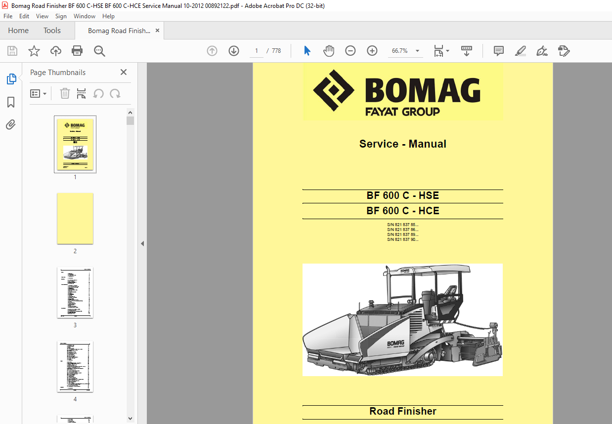
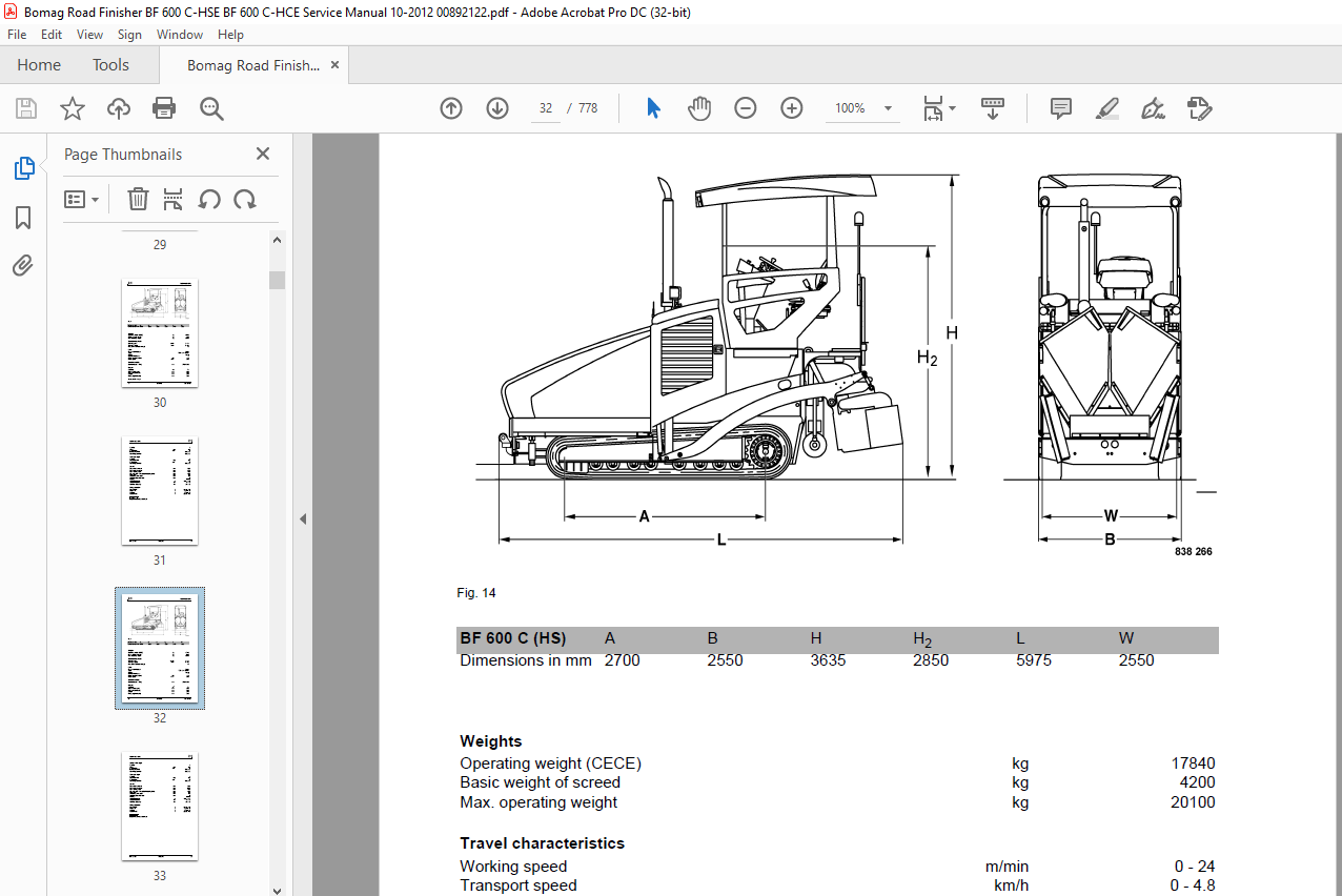
TABLE OF CONTENTS:
Bomag BF 600 C – HSE BF 600 C – HCE Road Finisher Service Manual 00892122 – PDF DOWNLOAD
eral 7
1.1 Introduction 8
1.2 Safety regulations 9
1.3 General repair instructions 13
1.4 Tightening torques 25
Technical data 29
2.1 Technical data 30
Maintenance 39
3.1 General notes on maintenance 40
3.2 Fuels and lubricants 41
3.3 Table of fuels and lubricants 44
3.4 Running-in instructions 45
3.5 Maintenance table 46
Fundamental electrics 49
4.1 Understanding wiring diagrams 50
4.2 Circuit symbols in the circuit diagram 55
4.3 Battery ground and analog ground 56
4.4 Processor signals 56
4.5 Current and voltage 57
4.6 Pulse Width Modulation (PWM) 59
4.7 Resistance 61
4.8 Series / parallel connection 63
4.9 Ohm’s law 65
4.10 Electrical energy 65
4.11 Formula diagram 66
4.12 Metrology 67
4.13 Diodes, relays, fuses 71
4.14 Inductive proximity switches 74
4.15 Plug connectors 75
4.16 Magnetic coil plug 76
4.17 Deutsch plug, series DT and DTM 78
4.18 Plugs and terminals in spring clamping technology 79
4.19 Batteries 83
4.20 Battery maintenance 87
4.21 Starting with jump wires 88
4.22 Main battery switch 88
4.23 Fuses 89
4.24 Replace heating elements 92
4.25 Failure codes, SAUER controller 95
Engine electrics 97
5.1 Installation location for engine control unit 98
5.2 EMR3 system components 99
5.3 Pin assignment of engine control EDC16 / EMR3 104
5.4 Camshaft speed sensor 109
5.5 Crankshaft speed sensor 110
5.6 Rail pressure sensor 113
Table of Contents
4 BOMAG 008 921 22
5.7 Fuel pressure sensor 115
5.8 Fuel control unit FCU 116
5.9 Injectors 118
5.10 Oil pressure sensor 119
5.11 Charge air temperature – charge air pressure sensor 120
5.12 EMR coolant temperature sensor 122
5.13 Glow plugs 124
5.14 Sensor, water in fuel, C39 125
5.15 Air filter vacuum switch, C40 125
5.16 Level probe coolant tank, C38 126
5.17 Diagnostics interface 126
5.18 Diagnose with CAN-bus 128
5.19 Diagnose with SERDIA 129
5.20 Fault code indication, diesel engine 132
5.21 EMR3 List of fault codes 133
5.22 Generator 206
5.23 Electric starter 215
Engine 223
6.1 Diesel engine 224
6.2 Engine description TCD 2013, 4 and 6 cylinder 225
6.3 Lubrication oil circuit TCD 2012 / 2013 229
6.4 Coolant circuit TCD 2012 / 2013 230
6.5 Fuel system TCD 2012 / 2013 231
6.6 Deutz Common Rail (DCR) injection system for TCD 2012 / 2013 233
6.7 Exhaust gas recirculation TCD 2012 / 2013 237
6.8 Wastegate – charge pressure controller on TCD-engines 238
6.9 Engine problems 240
6.10 Check the engine oil level 244
6.11 Changing engine oil and oil filter cartridge 244
6.12 Replace the fuel filter cartridges. 245
6.13 Changing the fuel filter, bleeding the fuel system 246
6.14 Check, clean the water separator 248
6.15 Check the coolant level 249
6.16 Replacing the coolant 249
6.17 Air filter maintenance 250
6.18 Adjust the valve clearance 252
6.19 Adjusting the control piston play 253
6.20 Clean the cooling fins on engine and hydraulic oil cooler 254
6.21 Check the engine mounts 255
6.22 Replace the crank case ventilation valve 256
6.23 Electronic injector test EMR 256
6.24 Engine conservation 257
6.25 Checking the condition and tension of the screed heating generator V-belt, tensioning
and if necessary replacing the V-belt 257
6.26 Check, tension, replace the V-belt 258
6.27 Special tools, Deutz engine (TCD 2013 2V) 260
Hydraulics 279
7.1 Hydraulic circuit 280
Table of Contents
008 921 22 BOMAG 5
7.2 Travel system 282
7.3 Actuator drive 313
7.4 Scraper chain drive 328
7.5 Vibration and tamper drive 339
7.6 Fan drive 355
Tests and adjustments 361
8.1 Checking and adjusting the vibration 362
8.2 Checking and adjusting the tamping process 366
8.3 Checking/adjusting the mobile screed 370
8.4 Checking/adjusting the hopper wings 372
8.5 Checking & adjusting the time for screed levelling 374
Central lubrication system 377
9.1 BF 600C with HC screed, 32 lubrication points 378
9.2 BF 600C with HC screed, 34 lubrication points 380
9.3 Filling the lubricant container 382
9.4 Electric pump 383
9.5 Integrated electronic control 387
9.6 Progressive distributor 391
9.7 Fault – Cause – Remedy 397
9.8 Repair of a blocked distributor 399
Suppliers documentation 401
10.1 Travel pump 403
10.2 Travel motor 557
10.3 Conveyor screws – scraper belt motor 651
10.4 Travel gear 669
Circuit diagrams 705
11.1 Hydraulic diagram 2542306 707
11.2 Wiring diagram DE006010 711
More products