$32
Bomag BMP 8500 Multi-purpose compactor Service Manual 00891577 – PDF DOWNLOAD
Bomag BMP 8500 Multi-purpose compactor Service Manual 00891577 – PDF DOWNLOAD
FILE DETAILS:
Bomag BMP 8500 Multi-purpose compactor Service Manual 00891577 – PDF DOWNLOAD
Language : English
Pages : 376
Downloadable : Yes
File Type : PDF
Size: 18.7 MB
DESCRIPTION:
Bomag BMP 8500 Multi-purpose compactor Service Manual 00891577 – PDF DOWNLOAD
S/N 101 720 11 ….
1.1Introduction:
- This manual addresses the professionally qualified personnel or the after sales service of BOMAG, and should be of help and assistance in correct and efficient repair and maintenance work.
- This manual describes the disassembly, dismantling, assembly, installation and repair of components and assemblies. The repair of components and assemblies is only described as this makes sense under due consideration of working means and spare parts supply.
Documentation
For the BOMAG machines described in this manual the following documentation is additionally available:
1Operating and maintenance instructions
2Spare parts catalogue
3Wiring diagram*
4Hydraulic diagram*
5Service Information
- Use only genuine BOMAG spare parts.
- Spare parts needed for repairs can be taken from the spare parts catalogue for the machine.
- These repair instructions are not subject of an updating service; for this reason we would like to draw your attention to our additional “Technical Service Bulletins”.
- In case of a new release all necessary changes will be included.
- In the course of technical development we reserve the right for technical modifications without prior notification.
- Information and illustrations in this manual must not be reproduced and distributed, nor must they be used for the purpose of competition. All rights according to the copyright law remain expressly reserved.
IMAGES PREVIEW OF THE MANUAL:
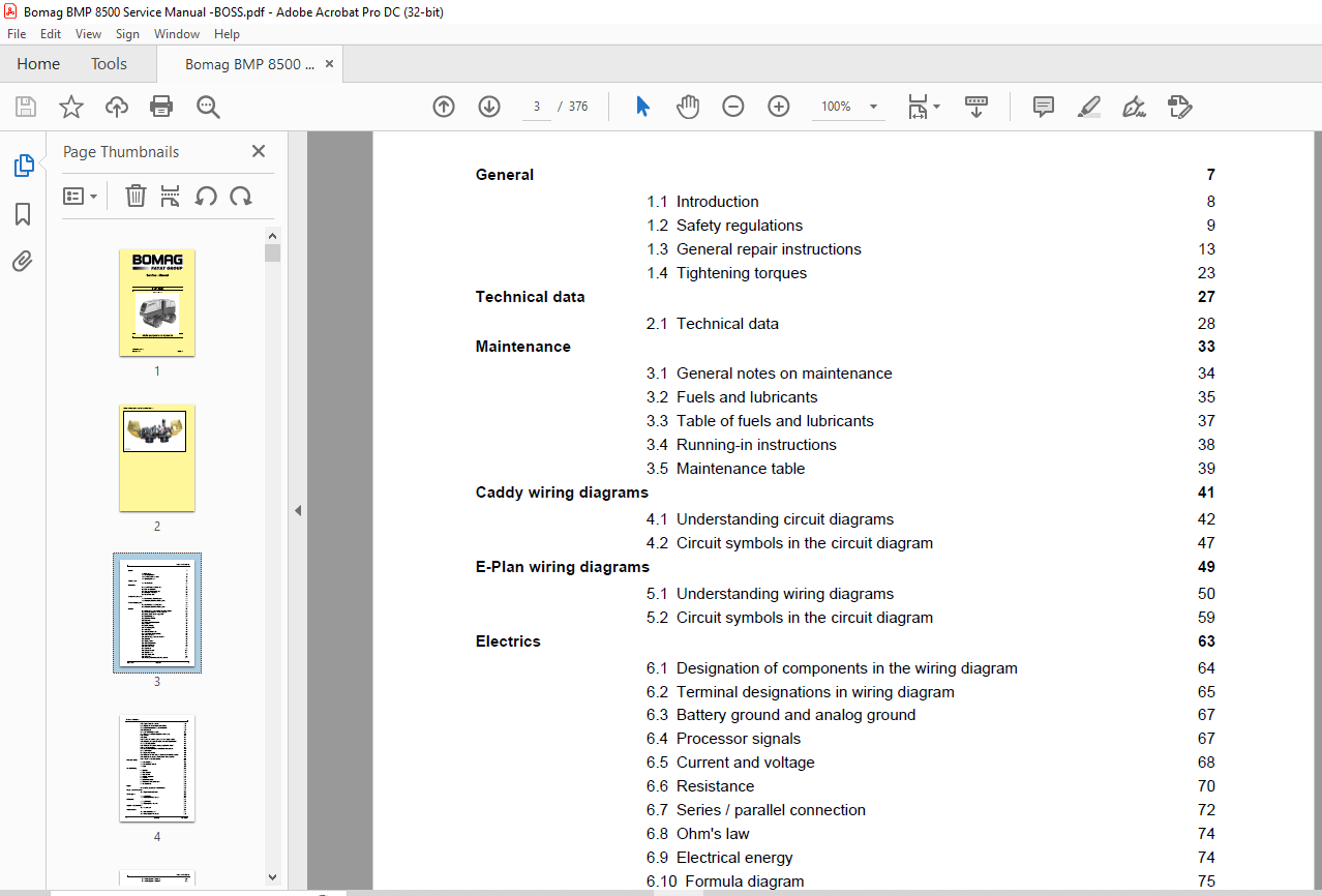
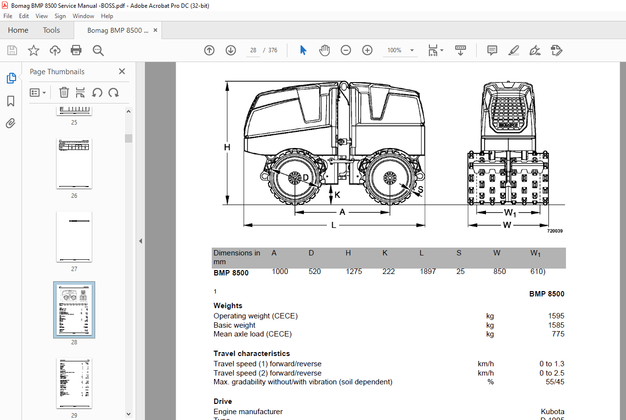
TABLE OF CONTENTS:
Bomag BMP 8500 Multi-purpose compactor Service Manual 00891577 – PDF DOWNLOAD
General 7
1.1 Introduction 8
1.2 Safety regulations 9
1.3 General repair instructions 13
1.4 Tightening torques 23 Technical data 27
2.1 Technical data 28 Maintenance 33
3.1 General notes on maintenance 34
3.2 Fuels and lubricants 35
3.3 Table of fuels and lubricants 37
3.4 Running-in instructions 38
3.5 Maintenance table 39 Caddy wiring diagrams 41
4.1 Understanding circuit diagrams 42
4.2 Circuit symbols in the circuit diagram 47 E-Plan wiring diagrams 49
5.1 Understanding wiring diagrams 50
5.2 Circuit symbols in the circuit diagram 59 Electrics 63
6.1 Designation of components in the wiring diagram 64
6.2 Terminal designations in wiring diagram 65
6.3 Battery ground and analog ground 67
6.4 Processor signals 67
6.5 Current and voltage 68
6.6 Resistance 70
6.7 Series / parallel connection 72
6.8 Ohm’s law 74
6.9 Electrical energy 74
6.10 Formula diagram 75
6.11 Metrology 76
6.12 Diodes, relays, fuses 80
6.13 Inductive proximity switches 83
6.14 Plug connectors 84
6.15 Deutsch plug, series DT and DTM 85
6.16 Batteries 89
6.17 Battery service 91
6.18 Main battery switch 92
6.19 Main battery fuse 92
6.20 External starting 93
6.21 Generator 93
6.22 Generator repair 100
6.23 Electric starter 104
6.24 Repair of starter 111
6.25 Glow plugs 115
6.26 Engine governor rod positioning solenoid 117
Table of Contents
4 BOMAG 008 915 77
6.27 Engine shut-down solenoid 119
6.28 Oil pressure and low oil pressure circuitry 122
6.29 Coolant temperature and power reduction 125
6.30 Wiring looms 127
6.31 BLM – Power/Logic Module 130
6.32 Checking the voltage supply for the control unit 132
6.33 Controls 140
6.34Fuses 141
6.35 Entering the machine type code into the display module 142
6.36 Replacing, recharging the radio remote control power pack 143
6.37 BOSS safety system 146
6.38 “Marriage” of transponder and protection field control 148
6.39 BOSS Service Mode 148
6.40 Safety field measurement of the Boss safety system 149
6.41 Fault indicator 149
6.42 Diagnostics concept 150
6.43 Problems with radio remote control Hetronic in radio operation 153
6.44 Problems with remote control Hetronic with spiral cable 155
6.45 Faults in BOSS safety system 158 Electronic control 159
7.1 with safety bow 161
7.2 with safety field control 193
7.3 Logic 227 Service Training 235
8.1General 237
8.2 Travel system 240
8.3 Travel motor 243
8.4 Multiple gear pump 245
8.5 Vibration 248
8.6 Control valve block 254
8.7 Hose connection centre frame 257
8.8 Hydraulic lines 258 Engine 265
9.1 Checking, adjusting the valve clearance 267 Repair overview for drum 269
10.1 Repair overview for drum 270 Travel system 271
11.1 Special tools 272
11.2 Repairing the travel system 273 Exciter unit 281
12.1 Special tools 282
12.2 Repairing the exciter unit. 283 Suppliers documentation 293
13.1 Travel motor 295 Circuit diagrams 309
14.1 Hydraulic diagram 21 311
14.2 Wiring diagram 724 002 09 319
Table of Contents
008 915 77 BOMAG 5
14.3 Wiring diagram 724 002 29 335
14.4 Wiring diagram 724 002 30 355
More products