$33
Bomag BMP 8500 Multi-purpose compactor Service Manual SN 10172011 – PDF DOWNLOAD
Bomag BMP 8500 Multi-purpose compactor Service Manual SN 10172011 – PDF DOWNLOAD
FILE DETAILS:
Bomag BMP 8500 Multi-purpose compactor Service Manual SN 10172011 – PDF DOWNLOAD
Language : English
Pages : 300
Downloadable : Yes
File Type : PDF
Size: 14.8 MB
DESCRIPTION:
Bomag BMP 8500 Multi-purpose compactor Service Manual SN 10172011 – PDF DOWNLOAD
Introduction:
- This manual addresses the professionally qualified personnel or the after sales service of BOMAG, and should be of help and assistance in correct and efficient repair and maintenance work.
- This manual describes the disassembly, dismantling, assembly, installation and repair of components and assemblies. The repair of components and assemblies is only described as this makes sense under due consideration of working means and spare parts supply.
Documentation
For the BOMAG machines described in this manual
the following documentation is additionally available:
1 Operating and maintenance instructions
2 Spare parts catalogue
3 Wiring diagram*
4 Hydraulic diagram*
5 Service Information
- Use only genuine BOMAG spare parts.
- Spare parts needed for repairs can be taken from the spare parts catalogue for the machine.
- These repair instructions are not subject of an updating service; for this reason we would like to draw your attention to our additional “Technical Service Bulletins”. In case of a new release all necessary changes will be included.
- In the course of technical development we reserve the right for technical modifications without prior notification.
- Information and illustrations in this manual must not be reproduced and distributed, nor must they be used for the purpose of competition. All rights according to the copyright law remain expressly reserved.
IMAGES PREVIEW OF THE MANUAL:
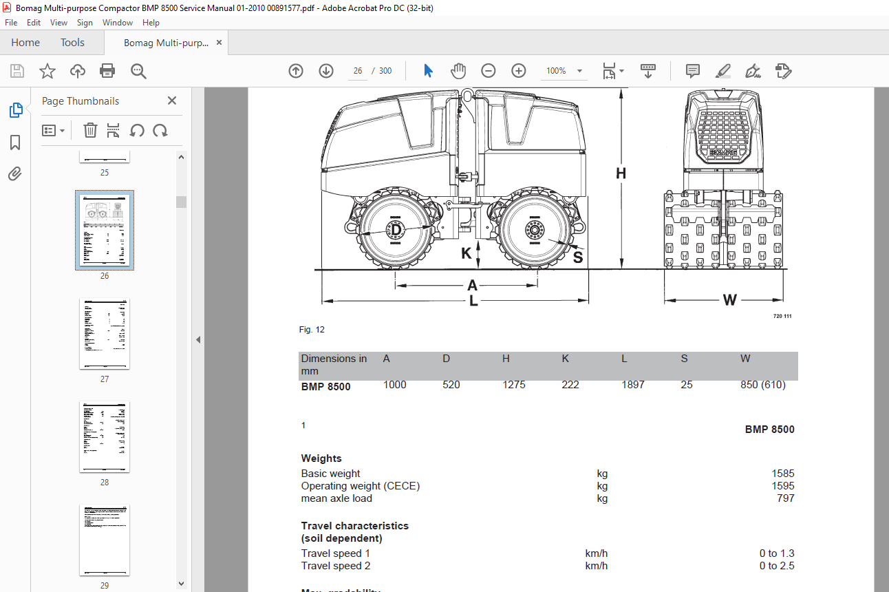
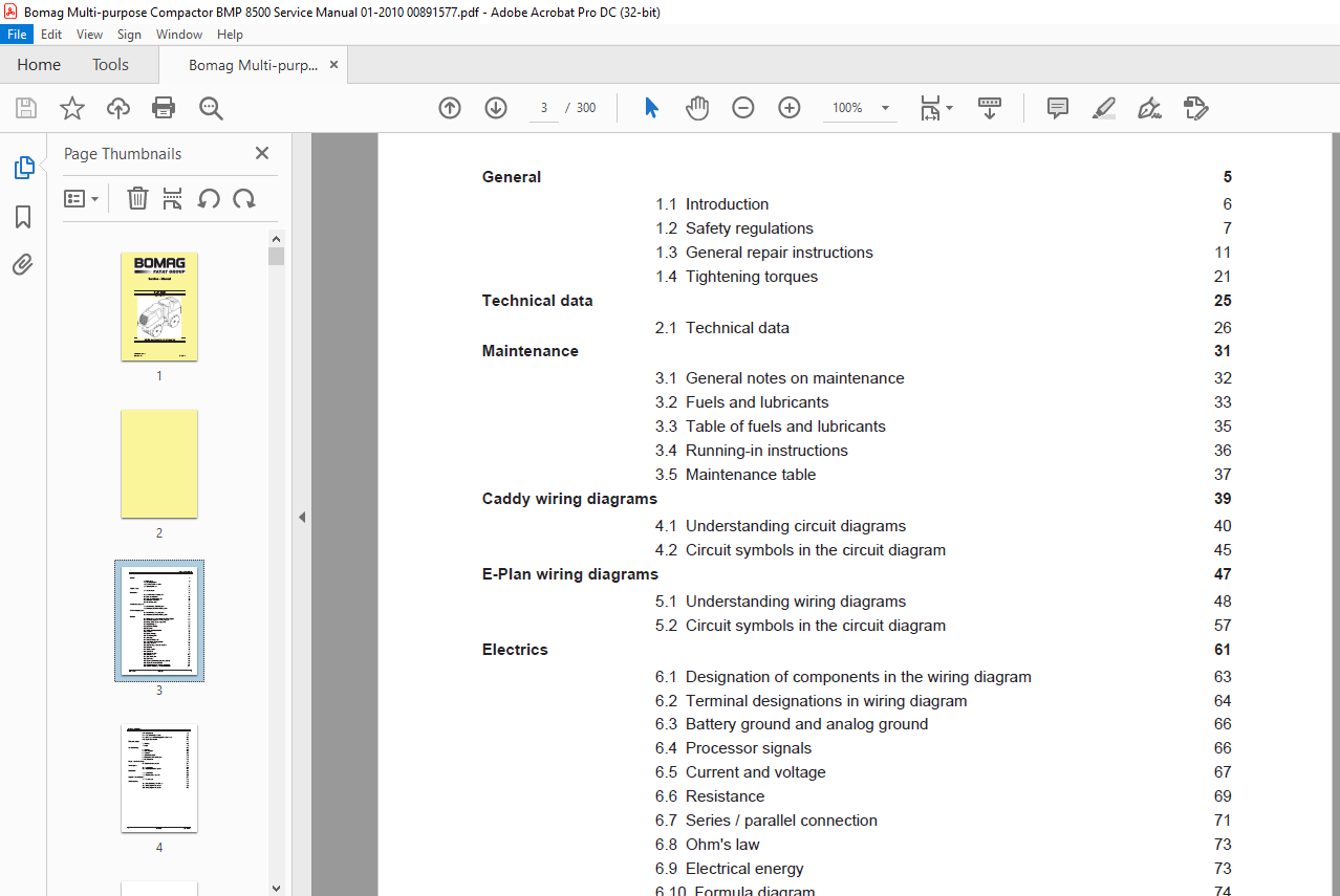
TABLE OF CONTENTS:
Bomag BMP 8500 Multi-purpose compactor Service Manual SN 10172011 – PDF DOWNLOAD
General 5
1.1 Introduction 6
1.2 Safety regulations 7
1.3 General repair instructions 11
1.4 Tightening torques 21
Technical data 25
2.1 Technical data 26
Maintenance 31
3.1 General notes on maintenance 32
3.2 Fuels and lubricants 33
3.3 Table of fuels and lubricants 35
3.4 Running-in instructions 36
3.5 Maintenance table 37
Caddy wiring diagrams 39
4.1 Understanding circuit diagrams 40
4.2 Circuit symbols in the circuit diagram 45
E-Plan wiring diagrams 47
5.1 Understanding wiring diagrams 48
5.2 Circuit symbols in the circuit diagram 57
Electrics 61
6.1 Designation of components in the wiring diagram 63
6.2 Terminal designations in wiring diagram 64
6.3 Battery ground and analog ground 66
6.4 Processor signals 66
6.5 Current and voltage 67
6.6 Resistance 69
6.7 Series / parallel connection 71
6.8 Ohm’s law 73
6.9 Electrical energy 73
6.10 Formula diagram 74
6.11 Metrology 75
6.12 Diodes, relays, fuses 79
6.13 Inductive proximity switches 82
6.14 Plug connectors 83
6.15 Deutsch plug, series DT and DTM 84
6.16 Batteries 90
6.17 Battery service 92
6.18 Generator 93
6.19 Generator repair 99
6.20 Electric starter 103
6.21 Repair of starter 110
6.22 Glow plugs 114
6.23 Engine governor rod positioning solenoid 116
6.24 Engine shut-down solenoid 118
6.25 Oil pressure and low oil pressure circuitry 121
6.26 Coolant temperature and power reduction 124
Table of Contents
4 BOMAG 008 915 77
6.27 Wiring looms 126
6.28 BLM – Power/Logic Module 129
6.29 Checking the voltage supply for the control unit 131
6.30 Diagnostics concept 139
Electronic control 143
7.1 Training 145
7.2 Logic 177
Service Training 185
8.1 General 187
8.2 Travel system 190
8.3 Vibration 197
8.4 Control valve block 202
8.5 Hose connection centre frame 205
8.6 Hydraulic lines 206
Repair overview for drum 213
9.1 Repair overview for drum 214
Travel system 215
10.1 Special tools 216
10.2 Repairing the travel system 217
Exciter unit 225
11.1 Special tools 226
11.2 Repairing the exciter unit. 227
Suppliers documentation 237
12.1 Travel motor 239
Circuit diagrams 253
13.1 Hydraulic diagram 724 301 06 255
13.2 Wiring diagram 724 002 09 263
13.3 Wiring diagram 724 002 29 279
More products