$36
Bomag BW 100 AD-4 BW 100 AC-4 BW 120 AD-4 BW 125 AD-4 BW 120 AC-4 BW 125 AC-4 Roller Service Manual
Bomag BW 100 AD-4 BW 100 AC-4 BW 120 AD-4 BW 125 AD-4 BW 120 AC-4 BW 125 AC-4 Tandem Vibratory Roller Service Manual 00891524 – PDF DOWNLOAD
FILE DETAILS:
Bomag BW 100 AD-4 BW 100 AC-4 BW 120 AD-4 BW 125 AD-4 BW 120 AC-4 BW 125 AC-4 Tandem Vibratory Roller Service Manual 00891524 – PDF DOWNLOAD
Language : English
Pages : 560
Downloadable : Yes
File Type : PDF
Size: 48.5 MB
DESCRIPTION:
Bomag BW 100 AD-4 BW 100 AC-4 BW 120 AD-4 BW 125 AD-4 BW 120 AC-4 BW 125 AC-4 Tandem Vibratory Roller Service Manual 00891524 – PDF DOWNLOAD
S/N 101 880 16 …. > / S/N 101 880 17 ….>
S/N 101 880 08 …. > / S/N 101 880 09 ….>
S/N 101 880 10 …. > / S/N 101 880 11 ….>
1.1Introduction:
- This manual addresses the professionally qualified personnel or the after sales service of BOMAG, and should be of help and assistance in correct and efficient repair and maintenance work.
- This manual describes the disassembly, dismantling, assembly, installation and repair of components and assemblies.
- The repair of components and assemblies is only described as this makes sense under due consideration of working means and spare parts supply.
Documentation
For the BOMAG machines described in this manual the following documentation is additionally available:
1Operating and maintenance instructions
2Spare parts catalogue
3Wiring diagram*
4Hydraulic diagram*
5Service Information
- Use only genuine BOMAG spare parts.
- Spare parts needed for repairs can be taken from the spare parts catalogue for the machine.
- These repair instructions are not subject of an updating service; for this reason we would like to draw your attention to our additional “Technical Service Bulletins”.
- In case of a new release all necessary changes will be included.
- In the course of technical development we reserve the right for technical modifications without prior notification.
- Information and illustrations in this manual must not be reproduced and distributed, nor must they be used for the purpose of competition. All rights according to the copyright law remain expressly reserved.
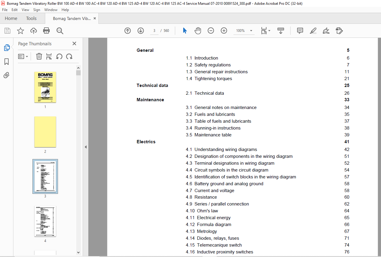
TABLE OF CONTENTS:
Bomag BW 100 AD-4 BW 100 AC-4 BW 120 AD-4 BW 125 AD-4 BW 120 AC-4 BW 125 AC-4 Tandem Vibratory Roller Service Manual 00891524 – PDF DOWNLOAD
General 5
1.1 Introduction 6
1.2 Safety regulations 7
1.3 General repair instructions 11
1.4 Tightening torques 21 Technical data 25
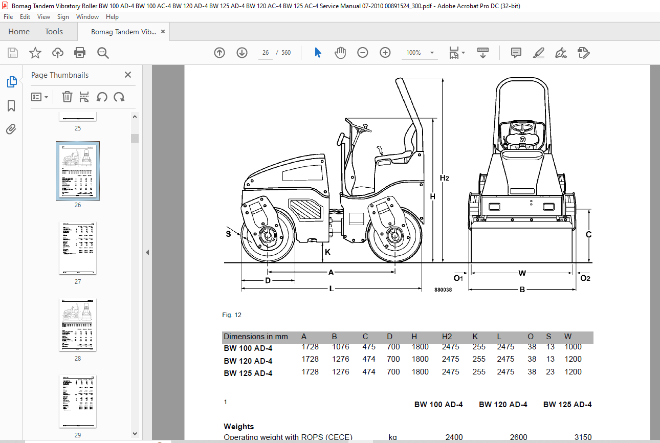
2.1 Technical data 26 Maintenance 33
3.1 General notes on maintenance 34
3.2 Fuels and lubricants 35
3.3 Table of fuels and lubricants 37
3.4 Running-in instructions 38
3.5 Maintenance table 39 Electrics 41
4.1 Understanding wiring diagrams 42
4.2 Designation of components in the wiring diagram 51
4.3 Terminal designations in wiring diagram 52
4.4 Circuit symbols in the circuit diagram 54
4.5 Identification of switch blocks in the wiring diagram 57
4.6 Battery ground and analog ground 58
4.7 Current and voltage 58
4.8 Resistance 60
4.9 Series / parallel connection 62
4.10 Ohm’s law 64
4.11 Electrical energy 65
4.12 Formula diagram 66
4.13 Metrology 67
4.14 Diodes, relays, fuses 71
4.15 Telemecanique switch 74
4.16 Inductive proximity switches 76
4.17 Angle sensors 77
4.18 Plug connectors 79
4.19 Magnetic coil plug 80
4.20 Deutsch plug, series DT and DTM 82
4.21 Plugs and terminals in spring clamping technology 89
4.22 Batteries 93
4.23 Starting with jump wires 95
4.24 Main fuse 96
4.25 Generator 97
4.26 Generator repair 103
4.27 Electric starter 107
4.28 Repair of starter 114
4.29 Glow plugs 118
4.30 Engine shut-down solenoid 119
4.31 Engine oil pressure monitoring 121
4.32 Coolant temperature monitoring 121
Table of Contents
4 BOMAG 008 915 24
4.33 Modules 122
4.34 Switching the vibration on 123
4.35 Switching the pressure sprinkler system on 123
4.36Fuses 124
4.37 Installation locations for electrical components 125 Description of the modules 143
5.1 Electric modules 145 Service Training 161
6.1 Service Training 163 Flushing and bleeding 235
7.1 Special tools for flushing 236
7.2 Flushing – general 241
7.3 Flushing schematic for front drum drive 243
7.4 Flushing the front drum drive 244
7.5 Flushing schematic for rear drum drive system 248
7.6 Flushing the rear drum drive 249
7.7 Flushing schematic, rear wheel drive motors 253
7.8 Flushing the rear wheel drive 254
7.9 Flushing schematic for vibration drive on AD-machines 258
7.10 Flushing schematic for vibration circuit on AC-machines 259
7.11 Flushing the vibration circuit 260
7.12 Bleeding the travel circuit 262 Drum 265
8.1 Special tools 266
8.2 Repair overview for drum 268
8.3 Removing and installing the drum 270
8.4 Dismantling the drum 275
8.5 Assembling the drum 281 Oscillating articulated joint 289
9.1 Special tools 290
9.2 Repair overview
Oscillating articulated joint 292
9.3 Removing and installing the oscillating articulated joint 294
9.4 Dismantling the oscillating articulated joint 296
9.5 Assembling the oscillating articulated joint 299 Suppliers documentation 305
10.1 Steering valve 307
10.2 Travel pump 341
10.3 Drum drive 399
10.4 Wheel drive 417 Circuit diagrams 493
11.1 Hydraulic diagram 880 100 50 495
11.2 Hydraulic diagram 880 100 52 499
11.3 Hydraulic diagram 880 100 55 503
11.4 Wiring diagram 880 100 63 507
11.5 Wiring diagram 880 100 64 533
IMAGES PREVIEW OF THE MANUAL:
More products