$40
Bomag BW 211 212 213 D-40 BW 211 212 213 PD-40C Single Drum Roller Service Manual 00891163 – PDF
Bomag BW 211 212 213 D-40 BW 211 212 213 PD-40C Single Drum Roller Service Manual 00891163 – PDF DOWNLOAD
FILE DETAILS:
Bomag BW 211 212 213 D-40 BW 211 212 213 PD-40C Single Drum Roller Service Manual 00891163 – PDF DOWNLOAD
Language : English
Pages : 972
Downloadable : Yes
File Type : PDF
Size: 103 MB
DESCRIPTION:
Bomag BW 211 212 213 D-40 BW 211 212 213 PD-40C Single Drum Roller Service Manual 00891163 – PDF DOWNLOAD
S/N 101 582 42 . . . . S/N 101 582 43 . . . . S/N 101 582 44 . . . .
S/N 101 583 02 . . . . S/N 101 583 03 . . . . S/N 101 582 55 . . . .
S/N 101 582 47 . . . . S/N 101 582 48 . . . . S/N 101 582 49 . . . .
1.1Introduction:
- This manual is intended to support expert mechanics in efficient repair and maintenance work. Whoever wants to do repair work himself should have been sufficiently trained and posses profound expert knowledge, he should limit his work only to those parts and components which will not affect the safety of the vehicle or the passengers. It is highly recommended to have repairs to critical systems, such as steering, brakes and travel drive, sole carried out by a BOMAG workshop. Untrained persons should NEVER UNTERTAKE SUCH REPAIR WORK.
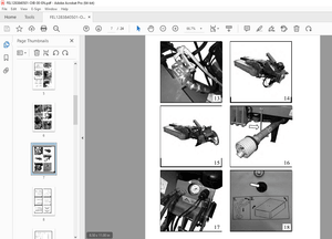
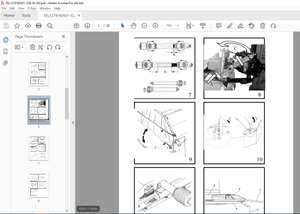
- The repair instructions describe the removal or dismantling and assembly of components and assembly groups. The repair of disassembled assembly groups is described as far as this makes sense with respect to available tools and spare parts supply and as far as it can be understood by a skilled mechanic.
Documentation
For the BOMAG machines described in this training manual the following documentation is additionally available:
1Operating and maintenance instructions
2Spare parts catalogue
3Wiring diagram*
4Hydraulic diagram*
5Service Information
- You should only use genuine BOMAG spare parts.
Spare parts needed for repairs can be taken from the spare parts catalogue for the machine. - This manual is not subject of any updating service; we would therefore like to draw your
attention to the additionally published “technical service information”. - In case of a new release all necessary changes will be included.
- In the course of technical development we reserve the right for technical modifications without prior notification.
- Information and illustrations in this manual must not be reproduced and distributed, nor must they be used for the purpose of competition. All rights according to the copyright law remain expressly reserved.
IMAGES PREVIEW OF THE MANUAL:
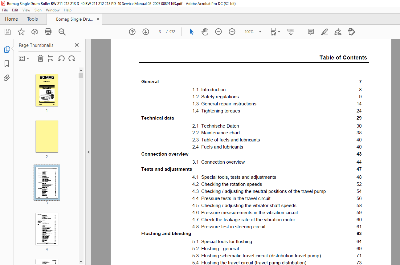
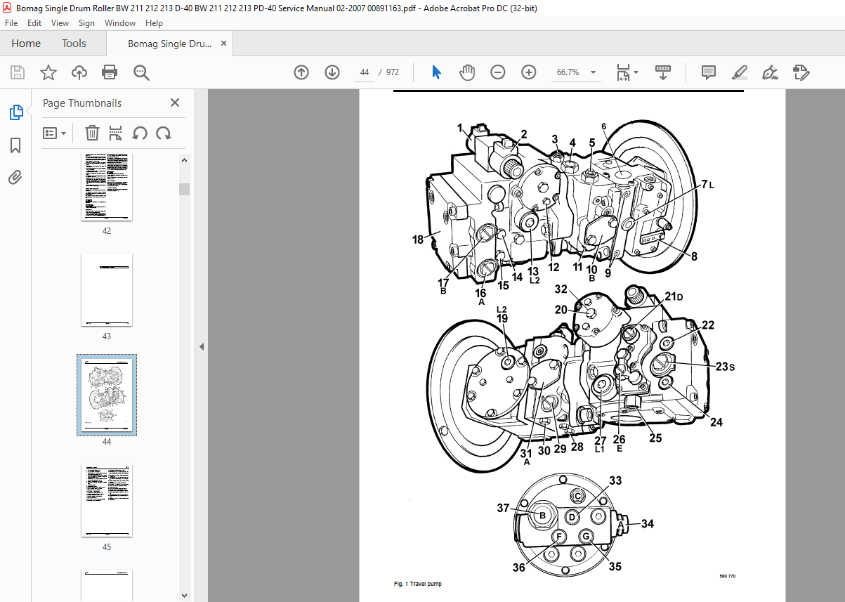
TABLE OF CONTENTS:
Bomag BW 211 212 213 D-40 BW 211 212 213 PD-40C Single Drum Roller Service Manual 00891163 – PDF DOWNLOAD
General 7
1.1 Introduction 8
1.2 Safety regulations 9
1.3 General repair instructions 14
1.4 Tightening torques 24 Technical data 29
2.1 Technische Daten 30
2.2 Maintenance chart 38
2.3 Table of fuels and lubricants 40
2.4 Fuels and lubricants 40 Connection overview 43
3.1 Connection overview 44 Tests and adjustments 47
4.1 Special tools, tests and adjustments 48
4.2 Checking the rotation speeds 52
4.3 Checking / adjusting the neutral positions of the travel pump 54
4.4 Pressure tests in the travel circuit 56
4.5 Checking / adjusting the vibrator shaft speeds 58
4.6 Pressure measurements in the vibration circuit 59
4.7 Check the leakage rate of the vibration motor 60
4.8 Pressure test in steering circuit 61 Flushing and bleeding 63
5.1 Special tools for flushing 64
5.2 Flushing – general 69
5.3 Flushing schematic travel circuit (distribution travel pump) 71
5.4 Flushing the travel circuit (travel pump distribution) 73
5.5 Flushing schematic travel circuit (distribution axle motor) 79
5.6 Flushing the travel circuit (axle motor distribution) 84
5.7 Flushing schematic for vibration drive 89
5.8 Flushing the vibration circuit 90
5.9 Bleeding the travel circuit 94
5.10 Bleeding the vibration circuit 96 Fundamental electrics 99
6.1 Understanding circuit diagrams 100
6.2 Terminal designations 104
6.3 Current and voltage 108
6.4 Resistance 112
6.5 Series / parallel connection 114
6.6 Ohm’s law 116
6.7 Electrical energy 116
6.8 Formula diagram 117
6.9 Metrology 118
6.10 Diodes, relays, fuses 120
6.11Batteries 123
6.12 Three-phase generator 126
6.13 Electric starter 133
Table of Contents
4 BOMAG 008 911 63
6.14 Telemecanique switch 136
6.15 Inductive proximity switches 139
6.16 Angle sensor with current output 140
6.17 Plug connectors 141
6.18 Deutsch plug, series DT and DTM 142
6.19 Plugs and terminals in spring clamping technology 148 Special tools, electrics 153
7.1 Special tools, electrics 154 Electronic modules 163
8.1 Vibration module 165 Speedometer Module 169
9.1 Speedometer module 171 Service Training 173
10.1 Electrics BEM (BOMAG Evib-meter) 175
10.2 Service Training 233 Engine 297
11.1 Diesel engine, general 299
11.2 Service side 300
11.3 Starter side 301
11.4 Lubrication oil circuit 302
11.5 Oil pressure switch and low oil pressure circuitry 304
11.6 Check the engine oil level 305
11.7 Changing engine oil and oil filter cartridges 306
11.8 Coolant circuit 308
11.9 Coolant temperature switch 310
11.10 Disassembling and assembling the coolant temperature switch 311
11.11 Replacing the thermostat 312
11.12 Checking the thermostat in disassembled state 313
11.13 Check the coolant level 314
11.14 Change the coolant 314
11.15 Clean the cooling fins on engine and hydraulic oil cooler 315
11.16 Three-phase generator 316
11.17 Fuel supply 318
11.18 Injection system 321
11.19 Injection pump replacement during service 322
11.20 Injection valve replacement during service 331
11.21 Checking / repairing injection valves 334
11.22 Fuel filter 339
11.23 Check, clean the water separator 341
11.24 Change the fuel pre-filter cartridge 341
11.25 Change the fuel filter cartridge 342
11.26 Checking the compression 343
11.27 Check, adjust the valve clearance 344
11.28 Boost fuel solenoid valve 346
11.29 Engine shut-down solenoid 347
11.30 Air filter 348
11.31 Cleaning, changing the dry air filter cartridge 349
Table of Contents
008 911 63 BOMAG 5
11.32 Heating flange on engine 351
11.33 Checking the heating flange control 354
11.34 Electric throttle control 355
11.35 Engine monitoring 357
11.36 Engine 359
11.37 Special tools, Deutz engine (BFM 2012) 361 Air conditioning system 373
12.1 Physical basics 375
12.2 Refrigerant R134a 378
12.3 Compressor oil / refrigeration oil 379
12.4 Working principle of the air conditioning system 380
12.5 Monitoring devices 380
12.6 Description of components 381
12.7 Checking the compressor oil level 387
12.8 Checking the magnetic clutch 388
12.9 Inspection and maintenance work 389
12.10 Checking, replacing the refrigerant compressor V-belt 389
12.11 Service the air conditioning 390
12.12 Drying and evacuation 393
12.13 Emptying in case of repair 393
12.14 Leak test 394
12.15 Filling instructions 395
12.16 Trouble shooting in refrigerant circuit, basic principles 398
12.17 Trouble shooting, refrigerant circuit diagram 402
12.18 Trouble shooting procedure 403
12.19 Steam table for R134a 413
12.20 Heating control / air conditioning control 419 Replacing the cab window panes 425
13.1 Assembly of window panes 426
13.2 Special tools 427
13.3 Auxiliary materials 428
13.4 Removing and installing the window pane 430 Drum 435
14.1 Special tools, drum, single drum rollers 436
14.2 Repair overview for drum 438
14.3 Removing and installing the drum 446
14.4 Repairing the drum 451
14.5 Disassembling and assembling the change-over weight 484
14.6 Changing the rubber buffers and adjusting the pretension 487 Oscillating articulated joint 491
15.1 Special tools 492
15.2 Repair overview oscillating articulated joint 494
15.3 Removing and installing the oscillating articulated joint 497
15.4 Dismantling the oscillating articulated joint 499
15.5 Assembling the oscillating articulated joint 504 Suppliers documentation 515
16.1 Travel pump series 90R 517
Table of Contents
6 BOMAG 008 911 63
16.2 Travel drive series 51 607
16.3 Vibration pump 42R 041 689
16.4 Vibration motor A10FM 727
16.5 MS/MSE 02 ….. 18 751
16.6 Axle DANA 192 801 Circuit diagrams 925
17.1 Wiring diagram 927
17.2 Hydraulic diagram 963
17.3 Hydraulic diagram 967
More products