$33
Bomag BW 216 D-40 PD-40 BW 218 D-40 Single Drum Roller Service Manual 00891812 – PDF DOWNLOAD
Bomag BW 216 D-40 PD-40 BW 218 D-40 Single Drum Roller Service Manual 00891812 – PDF DOWNLOAD
FILE DETAILS:
Bomag BW 216 D-40 PD-40 BW 218 D-40 Single Drum Roller Service Manual 00891812 – PDF DOWNLOAD
Language : English
Pages : 1446
Downloadable : Yes
File Type : PDF
Size: 73 MB
DESCRIPTION:
Bomag BW 216 D-40 PD-40 BW 218 D-40 Single Drum Roller Service Manual 00891812 – PDF DOWNLOAD
1.1Introduction:
- This manual addresses the professionally qualified personnel or the after sales service of BOMAG, and should be of help and assistance in correct and efficient repair and maintenance work.
- This manual describes the disassembly, dismantling, assembly, installation and repair of components and assemblies. The repair of components and assemblies is only described as this makes sense under due consideration of working means and spare parts supply.
Documentation:
For the BOMAG machines described in this manual the following documentation is additionally available:
1Operating and maintenance instructions
2Spare parts catalogue
3Service information
- Use only genuine BOMAG spare parts.
- Spare parts needed for repairs can be taken from the spare parts catalogue for the machine.
- This manual is not subject of an updating service; for this reason we would like to draw your attention to our additional “Technical Service Bulletins”.
- In case of a new release all necessary changes will be included.
- In the course of technical development we reserve the right for technical modifications without prior notification.
- Information and illustrations in this manual must not be reproduced and distributed, nor must they be used for the purpose of competition. All rights according to the copyright law remain expressly reserved.
IMAGES PREVIEW OF THE MANUAL:
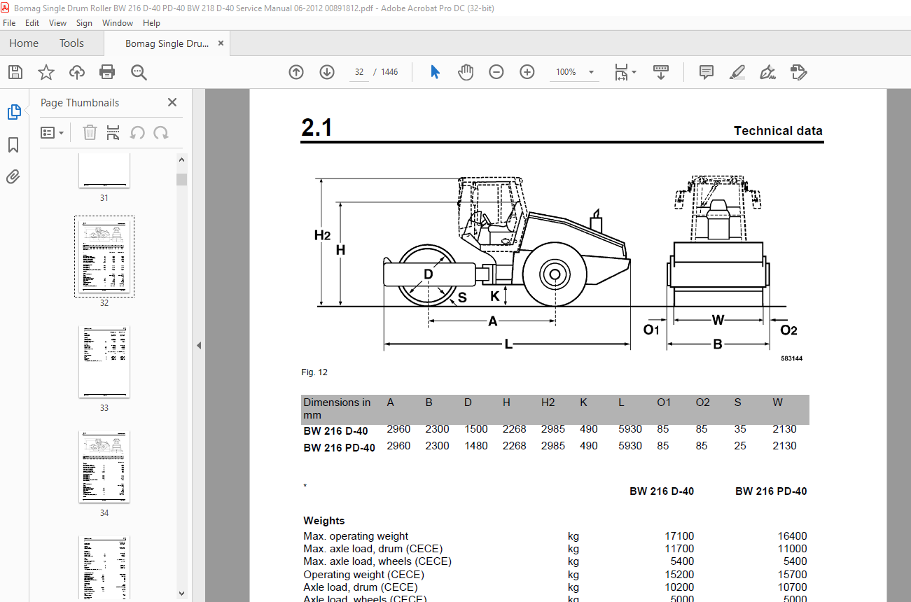

TABLE OF CONTENTS:
Bomag BW 216 D-40 PD-40 BW 218 D-40 Single Drum Roller Service Manual 00891812 – PDF DOWNLOAD
General 7
1.1 Introduction 8
1.2 Safety regulations 9
1.3 General repair instructions 14
1.4 Tightening torques 26
Technical data 31
2.1 Technical data 32
Maintenance 39
3.1 General notes on maintenance 40
3.2 Fuels and lubricants 41
3.3 Table of fuels and lubricants 44
3.4 Running-in instructions 45
Caddy wiring diagrams 47
4.1 Understanding circuit diagrams 48
4.2 Circuit symbols in the circuit diagram 53
4.3 Identification of switch blocks in the Caddy wiring diagram 54
4.4 Designation of components in the wiring diagram 55
4.5 Terminal designations in wiring diagram 56
E-Plan wiring diagrams 59
5.1 Understanding wiring diagrams 60
5.2 Circuit symbols in the circuit diagram 69
5.3 Identification of switch blocks in the wiring diagram 72
5.4 Designation of components in the wiring diagram 73
5.5 Terminal designations in wiring diagram 74
Electrics 77
6.1 Designation of components in the wiring diagram 78
6.2 Terminal designations in wiring diagram 79
6.3 Battery ground and analog ground 81
6.4 Current and voltage 81
6.5 Resistance 83
6.6 Series / parallel connection 85
6.7 Ohm’s law 87
6.8 Electrical energy 88
6.9 Formula diagram 89
6.10 Metrology 90
6.11 Diodes, relays, fuses 94
6.12 Telemecanique switch 97
6.13 Plug connectors 99
6.14 Magnetic coil plug 99
6.15 Deutsch plug, series DT and DTM 101
6.16 Plugs and terminals in spring clamping technology 106
6.17 Proximity switches 110
6.18 Level sensor in diesel tank (R03) 111
6.19 Differential pressure switch for hydraulic oil filter, B21 112
6.20 Acceleration transducer 114
6.21 Batteries 115
Table of Contents
4 BOMAG 008 918 12
6.22 Service the battery 119
6.23 Main battery fuse 120
6.24 Starting with jump wires 120
6.25 Generator 121
6.26 Replacing the voltage regulator 130
6.27 Electric starter 132
6.28 Coolant temperature switch 138
6.29 Oil pressure switch and low oil pressure circuitry 139
6.30 Boost fuel solenoid valve 141
6.31 Engine shut-down solenoid 142
6.32 Electric throttle control 143
6.33 Heating flange on engine 145
6.34 Checking the heating flange control 148
6.35 Engine monitoring 149
6.36 Overview of electric components 152
6.37 Operator’s stand, old design 163
6.38 Operator’s stand, new design 165
6.39 Cabin 166
6.40 Fuses, old design 167
6.41 Fuses, new design 168
6.42 Electronic control units 169
6.43 Checking the voltage supply for the control unit 172
6.44 Diagnostics concept 180
Electronic modules 183
7.1 BEM, BOMAG Evib-meter 185
7.2 Electrics module A68 249
7.3 Electric module K04 257
7.4 Electric module A72, old design 261
7.5 Electric module A108 267
Speedometer Module 271
8.1 Speedometer module 272
582 502 15 dust protection / 582 502 16 gasket 275
9.1 Assembling the dust protection 276
Hydraulics 281
10.1 Hydraulic circuit 282
10.2 Connection overview 284
10.3 Travel pump 075 286
10.4 Vibration pumps 42R041 & 42R055 292
10.5 Axial piston swash plate principle / pump 295
10.6 Troubleshooting axial piston pumps 297
10.7 Travel motor 51 C/D 110 300
10.8 Trouble shooting, variable displacement axial piston motor 302
10.9 Vibration motor A10FM 45 304
10.10 Vibration motor 90M 055 305
10.11 Axial piston swash plate principle / motor 307
10.12 External gear pumps 309
10.13 Travel circuit 311
Table of Contents
008 918 12 BOMAG 5
10.14 Adjust the parking brake 316
10.15 Stopping the machine, operating the parking brake 318
10.16 Towing in case of an engine failure 318
10.17 Vibration circuit 321
10.18 Steering circuit 326
10.19 Check the hydraulic oil level 332
10.20 Changing hydraulic oil and breather filter 332
10.21 Replace hydraulic oil filter 333
10.22 Changing the bypass filter 334
Tests and adjustments 335
11.1 Special tools, tests and adjustments 336
11.2 Adjusting the solenoid for engine speed control 340
11.3 Checking the rotation speeds 341
11.4 Checking / adjusting the neutral positions of the travel pump 343
11.5 Pressure tests in the travel circuit 345
11.6 Checking / adjusting the vibrator shaft speeds 347
11.7 Pressure measurements in the vibration circuit 348
11.8 Check the leakage rate of the vibration motor 349
11.9 Pressure test in steering circuit 350
Flushing and bleeding 353
12.1 Special tools for flushing 354
12.2 Flushing – general 359
12.3 Flushing schematic travel circuit (distribution travel pump) 361
12.4 Flushing the travel circuit (travel pump distribution) 363
12.5 Flushing schematic travel circuit (distribution axle motor) 369
12.6 Flushing the travel circuit (axle motor distribution) 374
12.7 Flushing schematic for vibration drive 379
12.8 Flushing the vibration circuit 380
12.9 Bleeding the travel circuit 384
12.10 Bleeding the vibration circuit 386
Air conditioning system 389
13.1 Physical basics 390
13.2 Refrigerant R134a 393
13.3 Compressor oil / refrigeration oil 394
13.4 Working principle of the air conditioning system 395
13.5 Monitoring devices 395
13.6 Description of components 396
13.7 Measuring the compressor oil level 402
13.8 Checking the magnetic clutch 402
13.9 Inspection and maintenance work 403
13.10 Checking, replacing the refrigerant compressor V-belt 404
13.11 Air conditioning service (old design) 405
13.12 Service the air conditioning 407
13.13 Drying and evacuation 410
13.14 Emptying in case of repair 410
13.15 Leak test 411
13.16 Filling instructions 412
13.17 Trouble shooting in refrigerant circuit, basic principles 415
Table of Contents
6 BOMAG 008 918 12
13.18 Trouble shooting, refrigerant circuit diagram 419
13.19 Trouble shooting procedure 420
13.20 Steam table for R134a 430
Cabin assembly 435
14.1 Preparations 437
14.2 Cabin assembly 438
14.3 Final function tests and checks 443
Replacing the cab window panes 445
15.1 Assembly of window panes 446
15.2 Special tools, cabin windows 447
15.3 Auxiliary materials 448
15.4 Removing and installing the window pane 450
Drum 455
16.1 Special tools, drum, single drum rollers 456
16.2 Repair overview for drum 458
16.3 Removing and installing the drum 467
16.4 Repairing the drum 473
16.5 Dismantling, assembling the change-over weights 504
16.6 Changing the rubber buffers and adjusting the pretension 507
Oscillating articulated joint 511
17.1 Special tools, oscillating articulated joint (BW177 to BW 216) 512
17.2 Repair overview oscillating articulated joint 514
17.3 Removing and installing the oscillating articulated joint 518
17.4 Dismantling the oscillating articulated joint 520
17.5 Assembling the oscillating articulated joint 525
Suppliers documentation 535
18.1 Travel pump 537
18.2 Vibration pump 691
18.3 Travel motor 761
18.4 Vibration motor 855
18.5 Vibration motor 879
18.6 Drum reduction gear 899
18.7 Steering valve 925
18.8 Axle 959
18.9 Diesel engine 1049
Circuit diagrams 1347
19.1 Hydraulic diagram 581 202 01 1349
19.2 Hydraulic diagram 581 202 06 1353
19.3 Wiring diagram 582 702 41 1357
More products