$38
Bomag BW177 D, DH, PDH-40 Single Drum Roller Instructions For Repair Manual – PDF DOWNLOAD
Bomag BW177 D, DH, PDH-40 Single Drum Roller Instructions For Repair Manual – PDF DOWNLOAD
FILE DETAILS:
Bomag BW177 D, DH, PDH-40 Single Drum Roller Instructions For Repair Manual – PDF DOWNLOAD
Language : English
Pages : 818
Downloadable : Yes
File Type : PDF
Size: 71.1 MB
DESCRIPTION:
Bomag BW177 D, DH, PDH-40 Single Drum Roller Instructions For Repair Manual – PDF DOWNLOAD
SERVICE AND REPAIR PRECAUTIONS:
ALWAYS inspect all slings, chains, or cables when lifting components. Be sure that they are properly tied,
fastened and balanced before lifting. Be sure that the lifting device is capable of retaining the
weight to be lifted.
NEVER attempt to lift heavy parts by hand when a lifting device should be used.
ALWAYS wear safety glasses when performing any maintenance or repair work on the machine.
NEVER attempt to remove or repair any component on the machine while the engine is running.
NEVER leave the machine and/or heavy parts in an unstable position during repair.
ALWAYS support the machine with sound blocking.
ALWAYS keep the machine and work area clear of lubricants and dirt.
ALWAYS use the correct tools for the repair procedures being done on the machine.
ALWAYS keep tools in a good and clean condition.
ALWAYS use approved parts that are designed for the machine being repaired. This helps to ensure
maximum service life of the machine.
ALWAYS be sure that all necessary nuts, bolts, snap rings, and other fastening devices are removed before
using force to remove components.
ALWAYS attach a sign in the machine operator’s area, stating “DO NOT OPERATE” when the machine is
being repaired.
ALWAYS observe ALL WARNING AND CAUTION statements given in the Operating Manual and Service
Manual and found on the machine decals.
General:• For repair work stand the machine on level and firm ground an shut down.• Secure the machine against unintentional rolling.• Secure the engine .reliably against unintentional starting.• Always mark a defective machine by attaching a respective note to the steering wheel.• During work secure the articulated joint with the articulation lock.• Use your protective outfit, such as hard hat and protective boots.• Keep unauthorized persons away from the machine while the repair work is going on.• Tools, lifting gear, lifting tackle, trestles and other auxiliary equipment must be fully functional and in safe condition.• Use only safe and approved lifting gear of sufficient load bearing capacity to removal and install parts or components from and to the machine.• Be careful with cleansing agents. Gasoline or other easily inflammable substances must not be used for cleaning purposes.• Cleaning and repair work on the fuel tank is dangerous. When repairing or cleaning the fuel tank do not smoke in the immediate vicinity, avoid ignition sparks and do not use open fire.• Always observe the welding instructions when performing welding work.
IMAGES PREVIEW OF THE MANUAL:
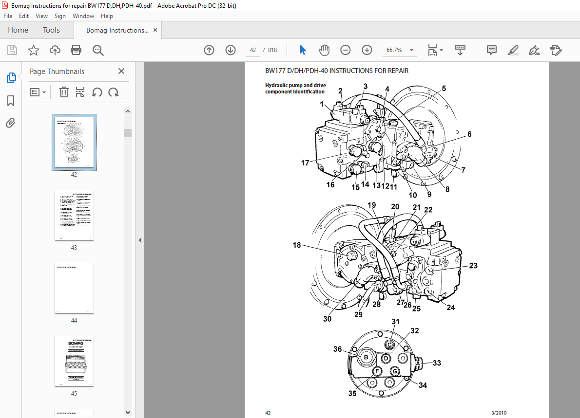
TABLE OF CONTENTS:
Bomag BW177 D, DH, PDH-40 Single Drum Roller Instructions For Repair Manual – PDF DOWNLOAD
SYMBOLS USED IN THIS MANUAL 8
SERVICE AND REPAIR PRECAUTIONS 10
Poisonous Substances 14
Engine 14
Air Conditioning System 14
Battery 15
Special safety notes 15
Electrics 16
Hydraulic system 17
Air conditioning system 18
Fuel hoses 20
Gaskets and mating surfaces 20
Feather keys and keyways 21
Ball and roller bearings 22
Screws and nuts 23
Tightening torque 23
Torques for bolts with metric unified threads 26
Torques for bolts with metric unified fine threads 27
Torques for screws treated with anti-seizure paste 28
The values specified in the table apply for screws: 29
Tightening torques for screws with UNF thread, 1 UNF Unified National Fine Thread Series, American
Unified Fine Thread 30
Tightening torques for screws with UNF thread 30
Specifications 31
General notes on maintenance 34
Fuels and lubricants 35
Engine oil 35
Approved engine oils 35
Fuels 36
Hydraulic oil 38
Running-in instructions 39
Maintenance schedule 40
Hydraulic pump and drive component identification 42
Test and adjustments flushing 45
Special Tools 48
Checking the rotary speeds 53
Checking I adjusting the mechanical neutral position of the travel pump 54
Pressure tests in the travel circuit 56
Measurement with quickly operated travel lever 57
Adjusting the vibrator shaft speed 58
Pressure tests in the vibration circuit 59
Checking the leak oil rate of the vibration motor 60
Pressure test in the steering circuit 62
Special tools for flushing 64
Special tools for flushing 64
Flushing – general 66
Hose routing for flushing 68
Flushing the travel circuit 70
Cleaning the hydraulic oil tank 70
Filter installation to flush the travel circuit 70
Bleeding the travel circuit 72
Flushing the hoses in the travel circuit 74
Flushing the drum drive motor 75
Flushing the travel motor 76
Function test 77
Flushing schematic, vibration drive 78
Flushing the vibration circuit 79
Flushing the entire system 79
Flushing the vibration circuit 80
Cleaning the hydraulic oil tank 80
Filter installation to flush the vibration circuit 80
Bleeding the vibration circuit 82
Flushing the hydraulic hoses 83
Flushing the vibration system 83
Function test 84
Maintenance of the flushing kit 84
Trouble shooting 85
General 88
Trouble shooting charts 90
Check the neutral position 91
Check the mechanical O-position 91
Adjust the mechanical 0-position 92
Check the servo control 92
The machine does not drive 93
Check the travel control cable 93
Check high and charge pressure 93
Check the magnetic coil of the brake valve 93
Check the brake releasing pressure 94
Check the steering/charge pump 95
Check the charge pressure relief valve 96
Check the flushing valve for the axle drive motor 96
Check the individual components 97
Check the drum drive motor 97
Check axle drive motor / travel pump 97
Check the servo control 98
Insufficient travel power, max speed not reached 99
Check the engine speed 99
Check trouble travel cable 99
Check the charge pressure 100
Check the steering/charge pump 101
Check the leakage of the brake 101
Check the charge pressure relief valve 102
Check the flushing valve for the axle drive motor 102
Check the individual components 103
Check the drum drive motor 103
Check axle drive motor / travel pump 103
Check the servo control 104
Hydraulic oil overheating 105
Check the thermostat valve 105
Check the multi-function valves 105
No vibration 106
Check the magnetic coil of the vibration valve 106
Check the pilot pressure 106
Check the vibration pump 107
Check the vibrator shaft bearings 107
Check the engine speed 108
Check the vibration pump 108
Vibrator shaft speed too low 108
Check flushing valve and flushing spool 109
Check the steering / charge pump 109
Check the charge pressure relief valve 110
Check the leak oil rate of the vibration motor 110
Check the vibration shaft bearings 111
Check the multi-function valve 111
Check the individual components 111
Check the way-valve 112
No steering function / steering sticky / end stops not reached 113
Check the steering pressure 113
Check the steering cylinders 113
Check the steering/charge pump 114
Drum 115
Special tools 118
Removing the drum 120
Removing and installing the drum 120
Installing the drum 122
Repair overview drum 124
Repairing the drum 126
Disassembling the bearing cover 127
Removing the vibrator shaft 128
Dismantling the vibrator shaft 129
Removing the cover 131
Installing the cover 132
Assembling the vibrator shaft 132
Assembling the vibrator shaft 135
Assembling the bearing cover 139
Dismantling, assembling the change-over weight 141
Dismantling the change-over weight 141
Assembling the change-over weight 142
Changing the rubber buffers 143
Oscillating articulated joint 145
Special tools 148
Removing and installing the oscillating articulated joint 149
Overview Articulated Joint 151
Dismantling the oscillating articulated joint 152
Assembling the oscillating articulated joint 156
Service Training 165
Diesel engine monitoring: 166
Travel pump 169
Cross-sectional view of travel pump 171
View of the rotating group 172
Description of function 173
Tandem pump 175
Tandem pump, connections an adjustment points 176
Servo control 178
Multi-function valves 180
Flushing valve 183
Axle drive motor 184
Rear axle 186
Front drum drive motor: Radial piston motor MSE 18 2 CX 187
Travel circuit: Drum drive with radial piston motor 190
Brake control: Travel motor in axle 191
Travel drive, components and test points 192
Travel pump: right hand side 193
Front travel motor, without brake (radial piston motor) 194
Rear travel motor: Axle motor 195
Rear travel motor: Axle motor 196
Travel lever console 197
Travel lever 198
Trouble shooting 199
Vibration system 200
Vibration system 202
Function 203
Vibration pump 204
High pressure relief valves 206
High pressure relief valves 207
High pressure relief valves 210
Vibration system: Components and test ports 211
Vibration pump 211
Vibration pump 212
Vibration motor 213
Trouble shooting 214
Trouble shooting 215
Steering pump 216
Working principle of the gear pumps 217
Steering valve 218
Articulated joint 220
Steering: Components and test ports 222
Steering pump 222
Vibration and noise damper 223
Steering valve 224
Trouble shooting 225
Electrics: Single drum rollers D-40 226
Function test: 226
Instrument cluster 227
Electric control cabinet with vibration module 227
Plug assignment with operating hour meter 229
Electrics 321
BW177D-40 321
BW177DH/PDH-40 355
Air Conditioning 393
Sauer Danfoss Series 90 Axial Piston Pumps and Motors 442
Sauer Danfoss Series 42 Axial Piston Closed Circuit Pump 530
Poclain MS Hydraulic Motors 598
Sauer Danfoss Series 51 Bent Axis Variable Motors 678
Dana 192 Axle 758
Detroit Locker NoSpin 794
More products