$35
Bomag MPH 122-2 Soil Stabilizer Asphalt Recycler Service Training Manual 00891787 – PDF DOWNLOAD
Bomag MPH 122-2 Soil Stabilizer Asphalt Recycler Service Training Manual 00891787 – PDF DOWNLOAD
FILE DETAILS:
Bomag MPH 122-2 Soil Stabilizer Asphalt Recycler Service Training Manual 00891787 – PDF DOWNLOAD
Language : English
Pages : 658
Downloadable : Yes
File Type : PDF
Size: 45.5 MB
DESCRIPTION:
Bomag MPH 122-2 Soil Stabilizer Asphalt Recycler Service Training Manual 00891787 – PDF DOWNLOAD
S/N 101 590 06 …. >
S/N 101 590 07 …. >
1.1Introduction:
- This manual addresses the professionally qualified personnel or the after sales service of BOMAG, and should be of help and assistance in correct and efficient repair and maintenance work.
- This manual describes the disassembly, dismantling, assembly, installation and repair of components and assemblies. The repair of components and assemblies is only described as this makes sense under due consideration of working means and spare parts supply.
Documentation
For the BOMAG machines described in this manual the following documentation is additionally available:
1Operating and maintenance instructions
2Spare parts catalogue
3Wiring diagram*
4Hydraulic diagram*
5Service Information
- Use only genuine BOMAG spare parts.
- Spare parts needed for repairs can be taken from the spare parts catalogue for the machine.
- These repair instructions are not subject of an updating service; for this reason we would like to draw your attention to our additional “Technical Service Bulletins”.
- In case of a new release all necessary changes will be included.
- In the course of technical development we reserve the right for technical modifications without prior notification.
- Information and illustrations in this manual must not be reproduced and distributed, nor must they be used for the purpose of competition. All rights according to the copyright law remain expressly reserved.
IMAGES PREVIEW OF THE MANUAL:
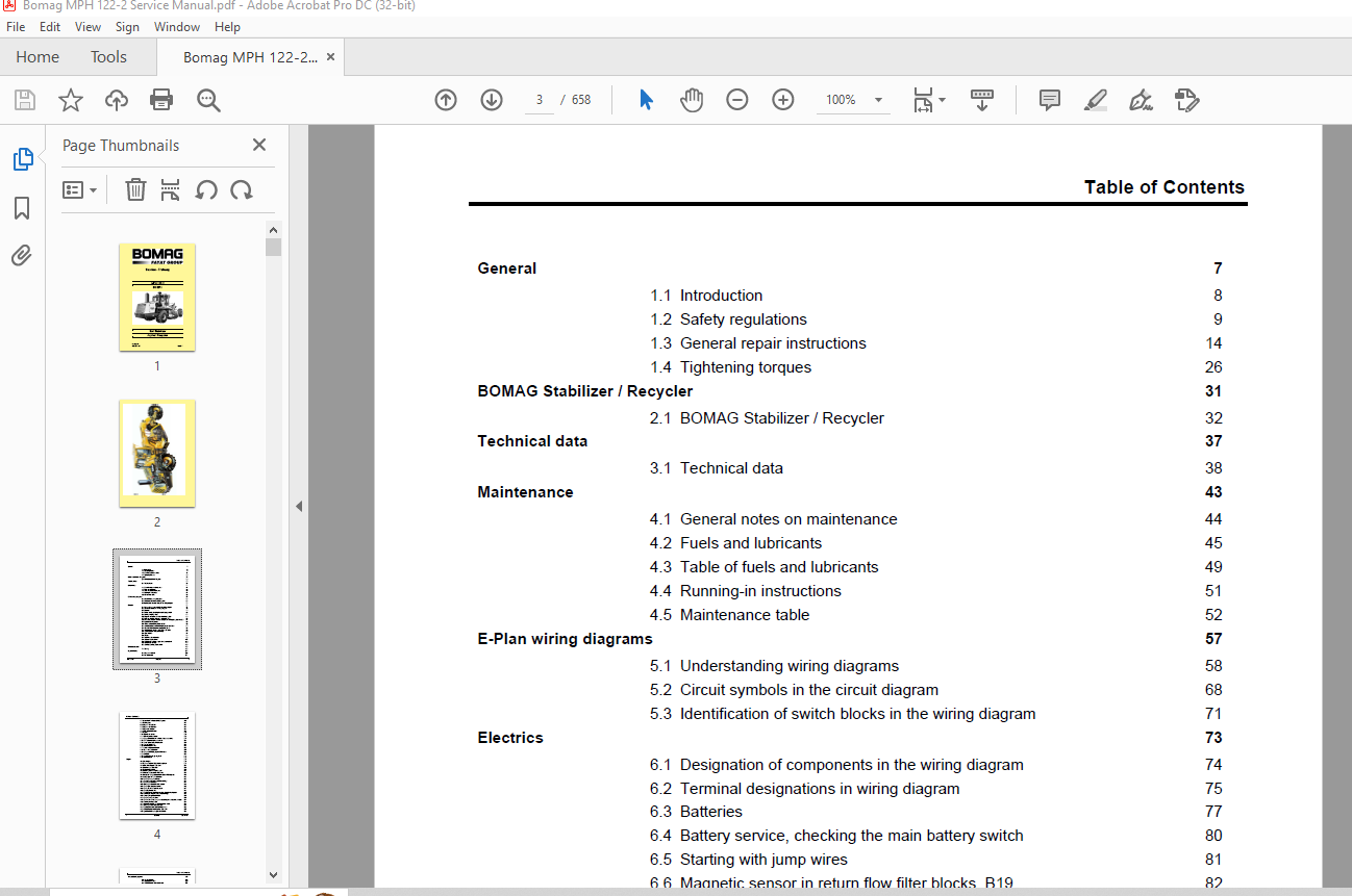
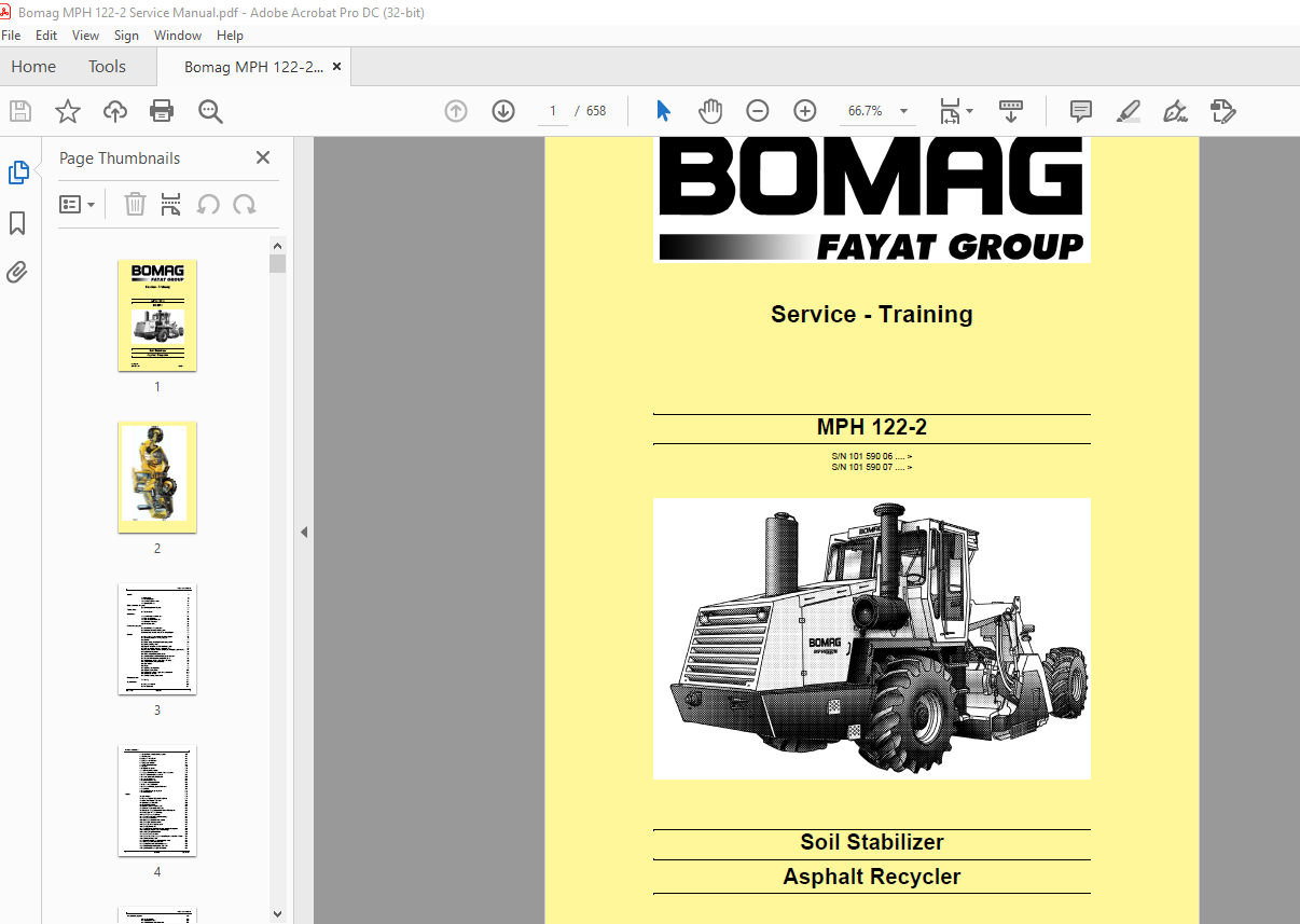
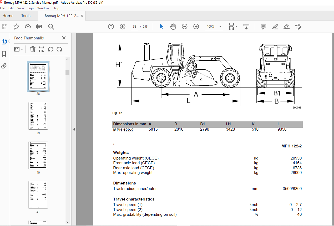
TABLE OF CONTENTS:
Bomag MPH 122-2 Soil Stabilizer Asphalt Recycler Service Training Manual 00891787 – PDF DOWNLOAD
General 7
1.1 Introduction 8
1.2 Safety regulations 9
1.3 General repair instructions 14
1.4 Tightening torques 26 BOMAG Stabilizer / Recycler 31
2.1 BOMAG Stabilizer / Recycler 32 Technical data 37
3.1 Technical data 38 Maintenance 43
4.1 General notes on maintenance 44
4.2 Fuels and lubricants 45
4.3 Table of fuels and lubricants 49
4.4 Running-in instructions 51
4.5 Maintenance table 52 E-Plan wiring diagrams 57
5.1 Understanding wiring diagrams 58
5.2 Circuit symbols in the circuit diagram 68
5.3 Identification of switch blocks in the wiring diagram 71 Electrics 73
6.1 Designation of components in the wiring diagram 74
6.2 Terminal designations in wiring diagram 75
6.3Batteries 77
6.4 Battery service, checking the main battery switch 80
6.5 Starting with jump wires 81
6.6 Magnetic sensor in return flow filter blocks, B19 82
6.7 Pressure switch in return flow filter block, B25 83
6.8 Differential pressure switches for hydraulic oil filter, B21, B22 and B42 84
6.9 Hydraulic oil temperature 85
6.10 Filling level switch hydraulic oil, B23 86
6.11 Charge pressure switch rotor pumps, B04 and B125 87
6.12 Pressure transducer for travel control, B112 88
6.13 Rotary speed sensors, B107, B108 and B109 89
6.14 Level sensor in diesel tank (R03) 90
6.15 Cab electrics 91
6.16Fuses 93
6.17 Machine related electrics 95
6.18 Electronic control units 107
6.19 Checking the voltage supply for the control unit 109
6.20 Diagnostics concept 117
6.21 Override function, ESX-control 120 Electronic control 121
7.1 Training 123 Engine electrics 201
8.1 Engine control unit 202
8.2 Pin assignment 204
Table of Contents
4 BOMAG 008 917 87
8.3 System faults indicated by flashing code 210
8.4 Flashing code 212
8.5 Diagnose with SERDIA 214
8.6 Diagnose with CAN-bus 217
8.7 Diagnostics interface 218
8.8 EMR3 List of fault codes 220
8.9 Sensors 291
8.10 Oil pressure sensor 293
8.11 Fuel temperature sensor 296
8.12 Charge air temperature – charge air pressure sensor 297
8.13 EMR coolant temperature sensor 300
8.14 Rotary speed sensor for camshaft 303
8.15 Sensor, water in fuel 304
8.16 Air filter vacuum switch 305
8.17 Coolant temperature sensor 306
8.18 Float switch, coolant tank 307
8.19 Charge control light, engine RPM-meter 308
8.20 Generator 309
8.21 Replacing the voltage regulator 318
8.22 Electric starter 320 Engine 327
9.1 Diesel engine 328
9.2 Engine description TCD 2015 V 6 cylinder 329
9.3 Lubrication oil circuit TCD 2015 331
9.4 Coolant circuit TCD 2015 332
9.5 Fuel circuit TCD 2015 333
9.6 Injection system (MVS) TCD 2015 336
9.7 Exhaust gas recirculation TCD 2015 339
9.8 Wastegate – charge pressure controller on TCD-engines 340
9.9 Check, adjust the valve clearance 342
9.10 Checking the engine oil level 343
9.11 Changing engine oil and oil filter cartridge 343
9.12 Check the coolant level 344
9.13 Checking the condition of the coolant 345
9.14 Checking/changing the coolant 346
9.15 Check, clean the water separator 347
9.16 Changing the fuel filter 348
9.17 Replacing the fuel pre-filter cartridge, bleed the fuel system 349
9.18 Cleaning, changing the dry air filter cartridge 350
9.19 Servicing the generator V-belt 352
9.20 Check the engine mounts 353
9.21 Check the fastening of engine / turbocharger / combustion air hoses 354
9.22 Cleaning the intercooler 354
9.23 Intercooler, draining off oil/condensation water 355
9.24 Checking the crankcase pressure 356
9.25 Replacing the crankcase ventilation valve 356
9.26 General trouble shooting chart TCD 2015 357
9.27 Special tools, Deutz engine (TCD 2015) 359
Table of Contents
008 917 87 BOMAG 5
Air conditioning system 379
10.1 Physical basics 380
10.2 Refrigerant R134a 383
10.3 Compressor oil / refrigeration oil 384
10.4 Working principle of the air conditioning system 385
10.5 Monitoring devices 385
10.6 Description of components 386
10.7 Measuring the compressor oil level 392
10.8 Checking the magnetic clutch 392
10.9 Inspection and maintenance work 393
10.10 Servicing the air conditioning compressor V-belt 394
10.11 Service the air conditioning 395
10.12 Drying and evacuation 397
10.13 Emptying in case of repair 398
10.14 Leak test 398
10.15 Filling instructions 399
10.16 Trouble shooting in refrigerant circuit, basic principles 402
10.17 Trouble shooting, refrigerant circuit diagram 406
10.18 Trouble shooting procedure 407
10.19 Steam table for R134a 417
10.20 Module A108 422 Hydraulics 423
11.1 Hydraulic circuit 424
11.2 List of components 426
11.3 Pumps on diesel engine 427
11.4 Pressure test bar 429
11.5 Travel pump A4VG56 EP 430
11.6 Rotor pump, A4VG180 EP 436
11.7 Axial piston swash plate principle. 442
11.8 Troubleshooting axial piston pumps 444
11.9 External gear pumps 447
11.10 Travel system 449
11.11 Trouble shooting, variable displacement axial piston motor 462
11.12 Rotor drive 464
11.13 Trouble shooting, variable displacement axial piston motor 474
11.14 Articulated steering 476
11.15 Control valve block 479
11.16 Hand pump 484
11.17 Raising/lowering the cabin 487
11.18 Towing 488
11.19 Intercooler 491
11.20 Cleaning the intercooler 495
11.21 Checking the hydraulic oil level 496
11.22 Changing hydraulic oil and breather filter 496
11.23 Checking the contamination of the hydraulic oil filters 498
11.24 Change the hydraulic oil fine filter 499 Water injection 501
12.1 Water dosing system 503
Table of Contents
6 BOMAG 008 917 87
12.2 Water dosing system nozzle change 515
12.3 Water sprinkler system, maintenance in the event of frost 515 Bitumen dosing system 517
13.1 Control elements 518
13.2 Bitumen dosing system 522
13.3 Binder circuit 537
13.4 Checking the reaction water level 539
13.5 Reaction water tank, maintenance in the event of frost 539
13.6 Checking the oil level for the reaction water pump 540
13.7 Checking the oil level in compressor and service unit 540
13.8 Checking the thermal oil level 541
13.9 Checking the contamination of the hydraulic oil filters 541
13.10 Checking the binder pump for leaks 542
13.11 Checking the spraying sections for leaks 542
13.12 Checking, cleaning the additional fuel filter water separator 543
13.13 Change the additional fuel filter 543
13.14 Changing the thermal oil 544
13.15 Compressor oil change 545
13.16 Cleaning the bitumen filter 545
13.17 Faults in binder dosing system 547 Circuit diagrams 549
14.1 Hydraulic diagram 593 301 24 551
14.2 Wiring diagram 42 555
14.3 Bitumen metering system electrics 615
14.4 Bitumen metering system hydraulics 633
14.5 Bitumen metering system pneumatics 637
14.6 Bitumen metering system bitumen 641
14.7 Bitumen metering system heating 645
14.8 Bitumen metering system water 649
14.9 Bitumen-water-compressed air 653
More products