$39
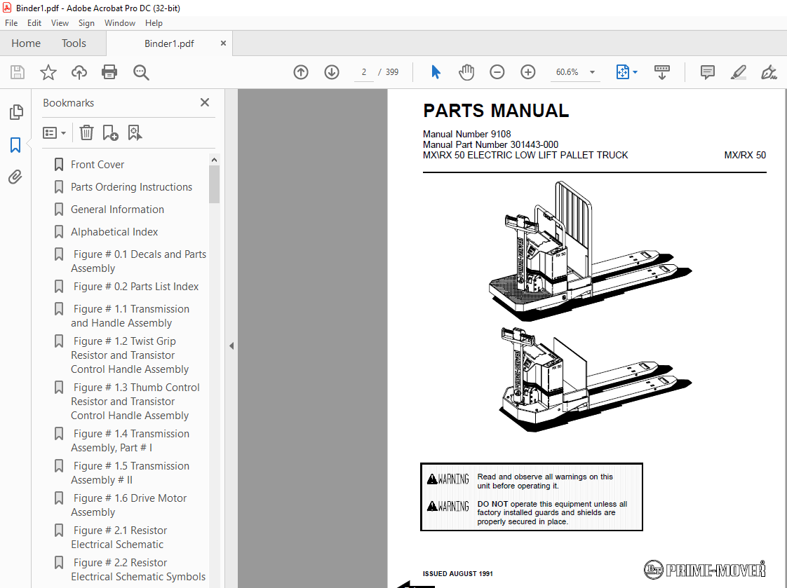
BT Forklift MX-50RX-50 ELECTRIC LOW LIFT PALLET TRUCK PARTS Manual – PDF DOWNLOAD
BT Forklift MX-50RX-50 ELECTRIC LOW LIFT PALLET TRUCK PARTS Manual – PDF DOWNLOAD
FILE DETAILS:
BT Forklift MX-50RX-50 ELECTRIC LOW LIFT PALLET TRUCK PARTS Manual – PDF DOWNLOAD
Language : English,
Pages :399
Downloadable : Yes
File Type : PDF
TABLE OF CONTENTS:
BT Forklift MX-50RX-50 ELECTRIC LOW LIFT PALLET TRUCK PARTS Manual – PDF DOWNLOAD
Front Cover 2
Parts Ordering Instructions 3
General Information 4
Alphabetical Index 5
Figure # 01 Decals and Parts Assembly 7
Figure # 02 Parts List Index 9
Figure # 11 Transmission and Handle Assembly 11
Figure # 12 Twist Grip Resistor and Transistor Control Handle Assembly 13
Figure # 13 Thumb Control Resistor and Transistor Control Handle Assembly 15
Figure # 14 Transmission Assembly, Part # I 17
Figure # 15 Transmission Assembly # II 19
Figure # 16 Drive Motor Assembly 21
Figure # 21 Resistor Electrical Schematic 23
Figure # 22 Resistor Electrical Schematic Symbols 24
Figure # 23 Resistor Control Wiring Harness Assembly 25
Figure # 24 Resistor Third Speed Control Wiring 27
Figure # 25 Resistor Third Speed Power Component Wiring 29
Figure # 26 Resistor Control Panel Assembly 31
Figure # 27 Contactor Assembly 33
Figure # 28 Forward & Rearward Contactor Assembly 35
Figure # 29 Third Speed Contactor Panel Assembly 37
Figure # 210 Resistor Fourth Speed Control Wiring 39
Figure # 211 Resistor Fourth speed Power Component Wiring 41
Figure # 212 Fourth Speed Contactor Panel Assembly 43
Figure # 213 Contactor Assembly 45
Figure # 214 Resistor Power Connector Assembly 47
Figure # 215 MX-50 Transistor Electrical Schematic 49
Figure # 216 MX-50 Transistor Electrical Schematic Symbols 50
Figure # 217 RX-50 Transistor Electrical Schematic 51
Figure # 218 RX-50 Transistor Electrical Schematic Symbols 52
Figure # 219 Transistor Control Wiring Harness Assembly 53
Figure # 220 Transistor Power Component Wiring 55
Figure # 221 Control Panel Assembly, 24 Volt 57
Figure # 222 Forward & Rearward Contactor Assembly 59
Figure # 223 High Speed Contactor Assembly, 24 Volt 61
Figure # 224 Transistor Power Connector Assembly 63
Figure # 225 Hydraulic Pump Motor Assembly 65
Figure # 227 MX-50, 24 Volt Drive Motor Assembly 69
Figure # 228 RX-50, 12 Volt Drive Motor Assembly 71
Figure # 229 RX-50, 24 Volt Drive Motor Assembly 73
Figure # 31 Hydraulic Schematic 75
Figure # 32 Hydraulic Schematic Symbols 76
Figure # 33 Resistor Hydraulic System 77
Figure # 34 Transistor Hydraulic System 79
Figure # 35 Pump and Motor Assembly 81
Figure # 36 Lift Cylinder Assembly 83
Figure # 41 Shielding Assembly 85
Figure # 42 Carrier Frame Assembly 87
Figure # 43 Caster Assembly 89
Figure # 44 Lift Frame Assembly 91
Figure # 45 Pallet Entry Rollers 95
Figure # 46 Skid Adapter and Package Guard Assembly 97
Figure # 47 Removable Load Backrest 99
Figure # 51 Battery Pack101
Figure # 52 Battery Pack Cable Assembly103
Figure # 53 Battery Pack Connector Assembly105
Figure # 71 Special Tools and Lubrications107
Numerical Index110
Back Cover123
Front Cover124
Parts Ordering Instructions125
Field Mofications125
General Information126
Alphabetical Index127
Figure # 01 Decals and Parts Assembly129
Figure # 02 Parts List Index131
Figure # 11 Transmission and Handle Assembly133
Figure # 12 Twist Grip Resistor/Transistor Control Handle Assembly135
Figure # 13 Thumb Control Resistor/Transistor Control Handle Assembly137
Figure # 14 Transmission Assembly Part # 1139
Figure # 15 Transmission Assembly Part # 2141
Figure # 16 Drive Motor Assembly143
Figure # 21 MX/RX 2 & 3 Speed Resistor Electrical Schematic145
Figure # 22 MX/RX 2 & 3 Speed Resistor Electrical Schematic Symbols146
Figure # 23 MX/RX 2 & 3 Speed Resistor Control Wiring Harness Assembly147
Figure # 24 MX/RX 2 & 3 Speed Resistor Control Wiring149
Figure # 25 MX/RX 2 & 3 Speed Resistor Power Component Wiring151
Figure # 26 MX/RX 2 Speed Resistor Control Panel Assembly153
Figure # 27 MX/RX 2 & 3 Speed Second Speed Contactor Assembly155
Figure # 28 MX/RX 2 & 3 Speed Forward & Rearward Contactor Assembly157
Figure # 29 RX 3 Speed Third Speed Contactor Panel Assembly159
Figure # 210 MX/RX 2 & 3 Speed Resistor Contactor Assembly161
Figure # 211 MX/RX 3 Speed Walkie/4 Speed Rider Resistor Electrical Schematic163
Figure # 212 Resistor Electrical Schematic Symbols164
Figure # 213 MX 3 Speed Walkie Resistor Control Wiring Harness Assembly165
Figure # 214 MX 3 Speed Walkie Resistor Third Speed Control Wiring167
Figure # 215 MX 3 Speed Walkie Resistor Third Speed Power Component Wiring169
Figure # 216 MX 3 Speed Walkie Third Speed Contactor Panel Assembly171
Figure # 217 RX 4 Speed Resistor Fourth Speed Control Wiring173
Figure # 218 RX 4 Speed Resistor Fourth Speed Power Component Wiring175
Figure # 219 MX/RX 3 Speed Walkie/4 Speed Rider Resistor Control Panel Assembly177
Figure # 220 MX/RX 3 & 4 Speed Second Speed Contactor Assembly179
Figure # 221 MX/RX 3 & 4 Speed Forward & Rearward Contactor Assembly181
Figure # 222 RX 4 Speed Fourth Speed Contactor Panel Assembly183
Figure # 223 RX 4 Speed Fourth Speed Contactor Assembly185
Figure # 224 MX/RX Resistor Power Connector Assembly187
Figure # 225 MX-50 Transistor Electrical Schematic189
Figure # 226 MX-50 Transistor Electrical Schematic Symbols190
Figure # 227 RX-50 Transistor Electrical Schematic191
Figure # 228 RX-50 Transistor Electrical Schematic Symbols192
Figure # 229 Transistor Control Wiring Harness Assembly193
Figure # 230 Transistor Power Component Wiring195
Figure # 231 Transistor Control Panel Assembly, 24 Volt197
Figure # 232 Forward & Rearward Contactor Assembly199
Figure # 233 High Speed Contactor Assembly201
Figure # 234 Transistor Power Connector Assembly203
Figure # 235 Pump Motor Assembly205
Figure # 236 MX/RX-50, 12 Volt Drive Motor Assembly207
Figure # 237 MX-50, 24 Volt Drive Motor Assembly209
Figure # 238 RX-50, 24 Volt Drive Motor Assembly211
Figure # 31 Hydraulic Schematic213
Figure # 32 Hydraulic Schematic Symbols214
Figure # 33 Resistor Hydraulic System215
Figure # 34 Transistor Hydraulic System217
Figure # 35 Pump and Motor Assembly219
Figure # 36 Lift Cylinder Assembly221
Figure # 41 Shielding Assembly223
Figure # 42 Carrier Frame Assembly225
Figure # 43 Caster Assembly227
Figure # 44 Lift Frame Assembly229
Figure # 45 Pallet Entry Rollers233
Figure # 46 Skid Adapter and Package Guard Assembly235
Figure # 47 Removable Load Backrest237
Figure # 51 Battery Pack239
Figure # 52 Battery Pack Cable Assembly241
Figure # 53 Battery Pack Connector Assembly243
Figure # 101 Special Tools and Lubrications245
Numerical Index248
Back Cover261
Front Cover262
Parts Ordering Instructions263
General Information264
Alphabetical Index265
Figure # 101383
Numerical Index386
Back Cover399
IMAGES PREVIEW OF THE MANUAL:

More products