$38
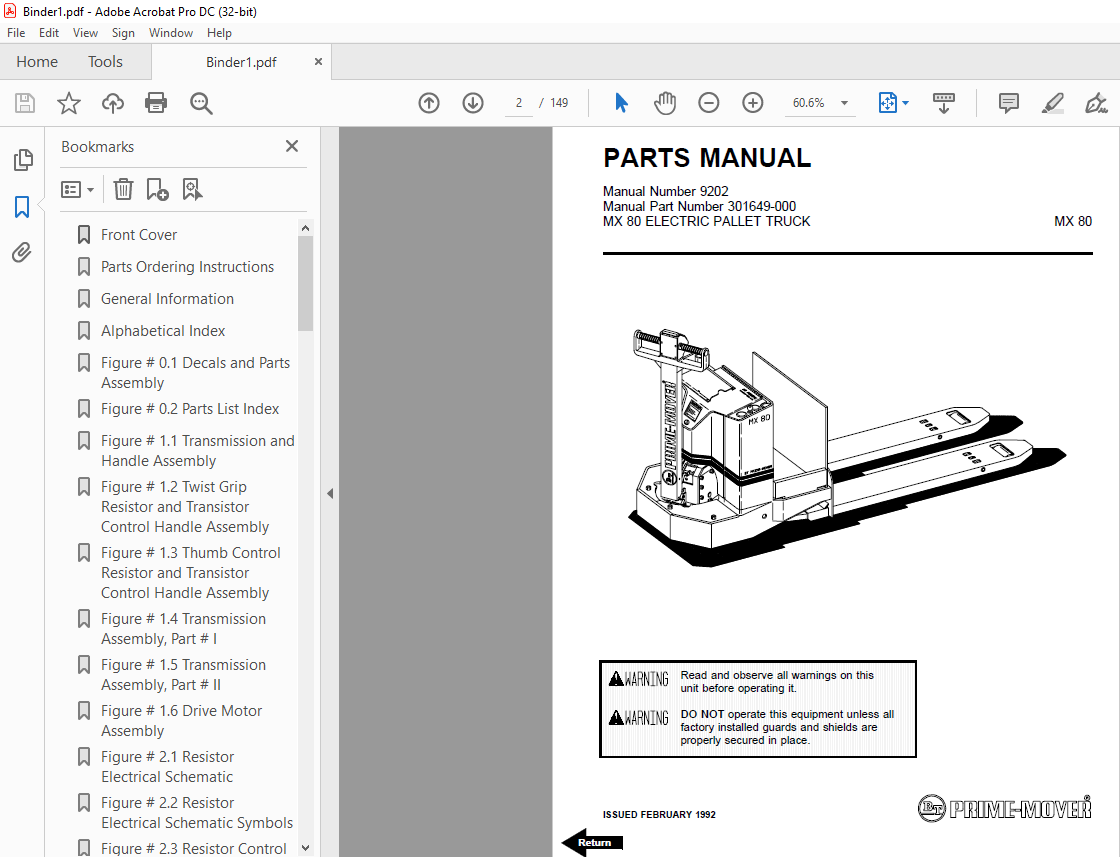
BT Forklift MX 80 ELECTRIC PALLET TRUCK PARTS MANUAL 9202 – PDF DOWNLOAD
BT Forklift MX 80 ELECTRIC PALLET TRUCK PARTS MANUAL 9202 – PDF DOWNLOAD
FILE DETAILS:
BT Forklift MX 80 ELECTRIC PALLET TRUCK PARTS MANUAL 9202 – PDF DOWNLOAD
Language : English,
Pages :149
Downloadable : Yes
File Type : PDF
TABLE OF CONTENTS:
BT Forklift MX 80 ELECTRIC PALLET TRUCK PARTS MANUAL 9202 – PDF DOWNLOAD
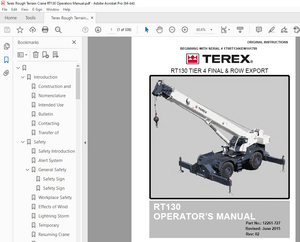
Front Cover 2
Parts Ordering Instructions 3
General Information 4
Alphabetical Index 5
Figure # 01 Decals and Parts Assembly 7
Figure # 02 Parts List Index 9
Figure # 11 Transmission and Handle Assembly 11
Figure # 12 Twist Grip Resistor and Transistor Control Handle Assembly 13
Figure # 13 Thumb Control Resistor and Transistor Control Handle Assembly 15
Figure # 14 Transmission Assembly, Part # I 17
Figure # 15 Transmission Assembly, Part # II 19
Figure # 16 Drive Motor Assembly 21
Figure # 21 Resistor Electrical Schematic 23
Figure # 22 Resistor Electrical Schematic Symbols 24
Figure # 23 Resistor Control Wiring Harness Assembly 25
Figure # 24 Resistor Third Speed Control Wiring 27
Figure # 25 Resistor Third Speed Power Component Wiring 29
Figure # 26 Resistor Control Panel Assembly 31
Figure # 27 Contactor Assembly 33
Figure # 28 Forward & Rearward Contactor Assembly 35
Figure # 29 Third Speed Contactor Panel Assembly 37
Figure # 210 Resistor Fourth Speed Control Wiring 39
Figure # 211 Resistor Fourth Speed Power Component Wiring 41
Figure # 212 Fourth Speed Contactor Panel Assembly 43
Figure # 213 Contactor Assembly 45
Figure # 214 Resistor Power Connector Assembly 47
Figure # 215 MX-80 Transistor Electrical Schematic 49
Figure # 216 MX-80 Transistor Electrical Schematic Symbols 50
Figure # 217 RX-80 Transistor Electrical Schematic 51
Figure # 218 RX-80 Transistor Electrical Schematic Symbols 52
Figure # 219 Transistor Control Wiring Harness Assembly 53
Figure # 220 Transistor Power Component Wiring 55
Figure # 221 Control Panel Assembly 57
Figure # 222 Forward & Rearward Contactor Assembly 59
Figure # 223 High Speed Contactor Assembly 61
Figure # 224 Transistor Power Connector Assembly 63
Figure # 225 Hydraulic Pump Motor Assembly 65
Figure # 226 MX-80, 12 Volt Drive Motor Assembly 67
Figure # 227 MX-80, 24 Volt Drive Motor Assembly 69
Figure # 228 RX-80, 12 Volt Drive Motor Assembly 71
Figure # 229 RX-80, 24 Volt Drive Motor Assembly 73
Figure # 31 Hydraulic Schematic 75
Figure # 32 Hydraulic Schematic Symbols 76
Figure # 33 Resistor Hydraulic System 77
Figure # 34 Transistor Hydraulic System 79
Figure # 35 Pump and Motor Assembly 81
Figure # 36 Lift Cylinder Assembly 83
Figure # 41 Shielding Assembly 85
Figure # 42 Carrier Frame Assembly 87
Figure # 43 Caster Assembly 89
Figure # 44 Lift Frame Assembly 91
Figure # 45 Pallet Entry Rollers 93
Figure # 46 Skid Adapter and Package Guard Assembly 95
Figure # 47 Removable Load Backrest 97
Figure # 101 Special Tools and Lubrications 99
Back Cover103
Front Cover104
Parts Ordering Instructions105
Field Modifications105
General Information106
Figure # 01 Decals and Parts Assembly107
Figure # 02 Parts List Index109
Figure # 11 Transmission and Handle Assembly111
Figure # 12 Twist Grip Resistor/Transistor Control Handle Assembly113
Figure # 13 Thumb Control Resistor/Transistor Control Handle Assembly115
Figure # 14 Transmission Assembly Part # 1117
Figure # 15 Transmission Assembly Part # 2119
Figure # 16 Drive Motor Assembly121
Figure # 21 Resistor Electrical Schematic123
Figure # 22 Resistor Electrical Schematic Symbols124
Figure # 23 Resistor Control Wiring Harness Assembly125
Figure # 24 Resistor Third Speed Control Wiring127
Figure # 25 Resistor Third Speed Power Component Wiring129
Figure # 26 Resistor Control Panel Assembly131
Figure # 27 Contactor Assembly133
Figure # 28 Forward & Rearward Contactor Assembly135
Figure # 29 Third Speed Contactor Panel Assembly137
Figure # 210 Resistor Fourth Speed Control Wiring139
Figure # 211 Resistor Fourth Speed Power Component Wiring141
Figure # 212 Fourth Speed Contactor Panel Assembly143
Figure # 213 Contactor Assembly145
Figure # 214 Resistor Power Connector Assembly147
Back Cover149
IMAGES PREVIEW OF THE MANUAL:
More products