$39
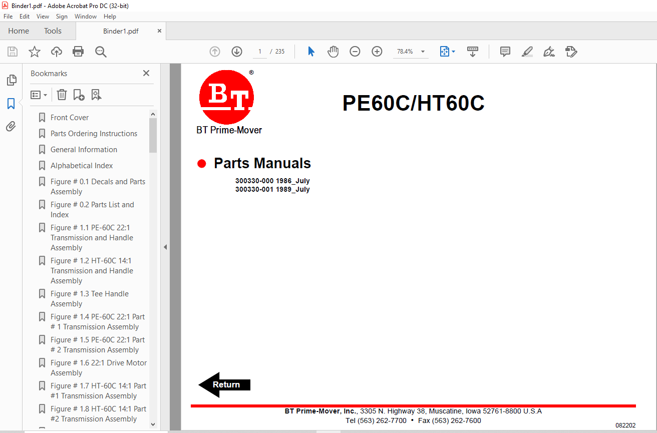
BT Forklift PE60C/HT60C Electric Center Control Lift Truck Parts Manual
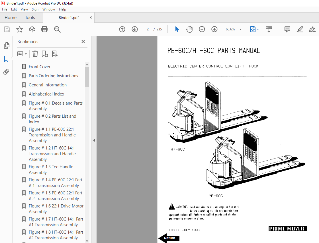
BT Forklift PE60C/HT60C Electric Center Control Lift Truck Parts Manual – PDF DOWNLOAD
FILE DETAILS:
BT Forklift PE60C/HT60C Electric Center Control Lift Truck Parts Manual – PDF DOWNLOAD
Language : English,
Pages :235
Downloadable : Yes
File Type : PDF
TABLE OF CONTENTS:
BT Forklift PE60C/HT60C Electric Center Control Lift Truck Parts Manual – PDF DOWNLOAD
Front Cover 2
Parts Ordering Instructions 3
General Information 4
Alphabetical Index 5
Figure # 01 Decals and Parts Assembly 7
Figure # 02 Parts List and Index 9
Figure # 11 PE-60C 22:1 Transmission and Handle Assembly 11
Figure # 12 HT-60C 14:1 Transmission and Handle Assembly 13
Figure # 13 Tee Handle Assembly 15
Figure # 14 PE-60C 22:1 Part # 1 Transmission Assembly 17
Figure # 15 PE-60C 22:1 Part # 2 Transmission Assembly 19
Figure # 16 22:1 Drive Motor Assembly 21
Figure # 17 HT-60C 14:1 Part #1 Transmission Assembly 23
Figure # 18 HT-60C 14:1 Part #2 Transmission Assembly 25
Figure # 21 Resistor Master Control Switch 27
Figure # 22 Resistor 4 Speed Master Control Switch 29
Figure # 23 EV-100/EV-1 SCR Master Control Switch 31
Figure # 24 PE-60C Resistor Electrical Schematic 33
Figure # 25 Resistor Electrical Schematic Symbols 34
Figure # 26 PE-60C Third Speed Control Wiring 35
Figure # 27 12 Volt PE-60C Third Speed Power Component Wiring 37
Figure # 28 24 Volt PE-60C Third Speed Power Component Wiring 39
Figure # 29 Control Panel Assembly 41
Figure # 210 Contactor Assembly 43
Figure # 211 Forward & Rearward Contactor Assembly 45
Figure # 212 Third Speed Contactor Panel Assembly 47
Figure # 213 PE-60C Third Speed Contactor Assembly 49
Figure # 214 HT-60C Resistor Electrical Schematic 51
Figure # 215 Resistor Electrical Schematic Symbols 52
Figure # 216 HT-60C Third Speed Control Wiring 53
Figure # 217 HT-60C Third Speed Power Component Wiring 55
Figure # 218 HT-60C Resistor Control Panel Assembly 57
Figure # 219 HT-60C Third Speed Contactor Panel Assembly 59
Figure # 220 HT-60C Fourth Speed Control Wiring 61
Figure # 221 HT-60C Fourth Speed Power Component Wiring 63
Figure # 222 HT-60C Fourth Speed Contactor Panel Assembly 65
Figure # 223 EV-100 SCR Trucks Electrical Schematic 67
Figure # 224 EV-100 SCR Truck Electrical Schematic Symbols 68
Figure # 225 EV-100 SCR Control Wiring 69
Figure # 226 HT-60C EV-100 SCR Two Speed Power Component Wiring 71
Figure # 227 EV-100 SCR Contactor Panel Assembly 73
Figure # 228 EV-100 SCR Forward & Rearward Contactor Assembly 75
Figure # 229 EV-100 1A Contactor Assembly 77
Figure # 230 HT-60C EV-100 SCR Two Speed Pump Contactor Panel Assembly 79
Figure # 231 EV-100 SCR Three Speed Power Component Wiring 81
Figure # 232 EV-100 SCR Three Speed Contactor Panel Assembly 83
Figure # 233 EV-100 SCR Two & Three Speed Control Panel 85
Figure # 234 Power Connector Assembly 87
Figure # 235 Hydraulic Pump Motor Assembly 89
Figure # 236 PE-60C Drive Motor Assembly 91
Figure # 237 HT-60C 14:1 Drive Motor Assembly 93
Figure # 238 Wiring Assembly for Cold Storage 95
Figure # 31 Hydraulic Schematic 97
Figure # 32 Hydraulic Schematic Symbols 98
Figure # 33 Hydraulic System 99
Figure # 34 Pump and Motor Assembly101
Figure # 35 Lift Cylinder Assembly103
Figure # 41 Shielding Assembly105
Figure # 42 Carrier Frame Assembly107
Figure # 43 Caster Assembly109
Figure # 44 Lift Frame Assembly111
Figure # 45 Pallet Entry Rollers113
Figure # 46 Rider Compartment and Padding Assembly115
Figure # 61 Special Tools and Lubrications117
Numerical Index120
Back Cover135
Front Cover136
Warranty137
Parts Ordering Instructions138
General Information139
Figure # 1 Decal and Parts Assembly141
Figure # 2 Parts List and Service Reference Index143
Figure # 3 Shield Assembly145
Figure # 4 Transmission and Handle Assembly147
Figure # 5 Tee Handle Assembly149
Figure # 6 3 Speed Master Control Switch Assembly151
Figure # 7 4 Speed Master Control Handle Assembly153
Figure # 8 PE-60C 22:1 Transmission Assembly155
Figure # 9 PE-60C 22:1 Drive Motor Assembly157
Figure # 10 Drive Motor 12 Volt159
Figure # 11 Drive Motor 24 Volt161
Figure # 12 HT-60C 14:1 Transmission Assembly163
Figure # 13 Drive Motor 24 Volt165
Figure # 14 PE-60C Electrical Schematic167
Figure # 15 HT-60C Electrical Schematic168
Figure # 16 Electrical Schematic Symbols169
Figure # 17 PE-60C 3 Speed Control Wiring Harness171
Figure # 18 12 Volt PE-60C 3 Speed Power Components173
Figure # 19 24 Volt PE-60C 3 Speed Power Components175
Figure # 20 PE-60C Control Panel Assembly177
Figure # 21 GE Contactor Assembly179
Figure # 22 GE Contactor Assembly181
Figure # 23 PE-60C 3 Speed Panel Assembly183
Figure # 24 HT-60C 3 Speed Control Wiring Harness185
Figure # 25 HT-60C 3 Speed Power Components187
Figure # 26 HT-60C Control Panel Assembly189
Figure # 27 GE Contactor Assembly191
Figure # 28 HT-60C 3 Speed Panel Assembly193
Figure # 29 HT-60C 4 Speed Control Wiring Harness195
Figure # 30 HT-60C 4 Speed Power Components197
Figure # 31 HT-60C 4 Speed Panel Assembly199
Figure # 32 Contactor Assembly201
Figure # 33 Power Connector Assembly203
Figure # 34 Wiring Assembly for Cold Storage205
Figure # 35 Hydraulic Schematic207
Figure # 36 Hydraulic Schematic Symbols208
Figure # 37 Hydraulic System209
Figure # 38 Hydraulic Pump and Motor Assembly211
Figure # 39 Motor Assembly213
Figure # 40 Cylinder Assembly215
Figure # 41 Lift Frame Assembly217
Figure # 42 Carrier Frame Assembly219
Figure # 43 Spring Loaded Caster Assembly221
Figure # 44 Pallet Entry Rollers223
Numerical Index225
Back Cover235
IMAGES PREVIEW OF THE MANUAL:
More products