$38
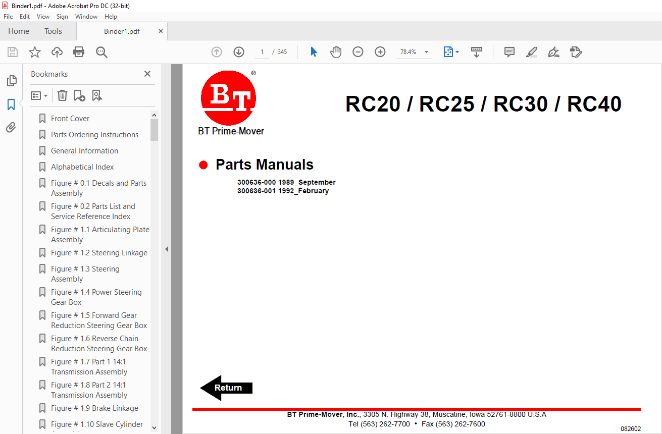
BT Forklift RC20 RC25 RC30 RC40 ELECTRIC COUNTERBALANCED RIDER TRUCK Parts Manual – PDF DOWNLOAD
BT Forklift RC20 RC25 RC30 RC40 ELECTRIC COUNTERBALANCED RIDER TRUCK Parts Manual – PDF DOWNLOAD
FILE DETAILS:
BT Forklift RC20 RC25 RC30 RC40 ELECTRIC COUNTERBALANCED RIDER TRUCK Parts Manual – PDF DOWNLOAD
Language : English,
Pages :345
Downloadable : Yes
File Type : PDF
TABLE OF CONTENTS:
BT Forklift RC20 RC25 RC30 RC40 ELECTRIC COUNTERBALANCED RIDER TRUCK Parts Manual – PDF DOWNLOAD
Front Cover 2
Parts Ordering Instructions 3
General Information 4
Alphabetical Index 5
Figure # 01 Decals and Parts Assembly 7
Figure # 02 Parts List and Service Reference Index 9
Figure # 11 Articulating Plate Assembly 11
Figure # 12 Steering Linkage 13
Figure # 13 Steering Assembly 15
Figure # 14 Power Steering Gear Box 17
Figure # 15 Forward Gear Reduction Steering Gear Box 19
Figure # 16 Reverse Chain Reduction Steering Gear Box 21
Figure # 17 Part 1 14:1 Transmission Assembly 23
Figure # 18 Part 2 14:1 Transmission Assembly 25
Figure # 19 Brake Linkage 27
Figure # 110 Slave Cylinder Assembly 29
Figure # 111 Master Cylinder Assembly 31
Figure # 112 Master Control Switch Handle Assembly 33
Figure # 21 EV-100/EV-1 SCR Master Control Switch 35
Figure # 22 EV-100 Electrical Schematic 37
Figure # 23 Electrical Schematic Symbols 38
Figure # 24 EV-100 Control Wiring 39
Figure # 25 EV-100 Power Component Wiring 41
Figure # 26 EV-100 SCR Contactor Panel Assembly 43
Figure # 27 EV-100 SCR Control Panel 45
Figure # 28 EV-100 SCR Forward & Rearward Contactor Assembly 47
Figure # 29 EV-100 1A Contactor Assembly 49
Figure # 210 EV-100 SCR Power Steering Contactor Assembly 51
Figure # 211 Power Connector Assembly 53
Figure # 212 Pump Motor Assembly 55
Figure # 213 Drive Motor Assembly 57
Figure # 214 Power Steering Motor Assembly 59
Figure # 215 Limit Switch Wiring Harness Assembly 61
Figure # 216 Warning Light Assembly 63
Figure # 217 Wiring Assembly for Cold Storage 65
Figure # 31 Hydraulic Schematic 67
Figure # 32 Hydraulic Schematic Symbols 68
Figure # 33 Lift Pump and Related Parts 69
Figure # 34 Two/Three Spool Control Valve Assembly 71
Figure # 35 24 Volt Lift Pump and Motor Assembly 73
Figure # 36 Lift Pump Assembly 75
Figure # 37 Two Stage Full Freelift Cylinders and Related Parts 77
Figure # 38 Cylinder Assembly 79
Figure # 39 Cylinder Assembly 81
Figure # 310 Two Stage Cylinder and Related Parts 83
Figure # 311 Two Stage Lift Cylinder Assembly 85
Figure # 312 Three Stage Cylinder and Related Parts 87
Figure # 313 Three Stage Staging Cylinder Assembly 89
Figure # 314 Three Stage Freelift Cylinder Assembly 91
Figure # 315 Tilt Cylinder and Related Parts 93
Figure # 316 Tilt Cylinder Assembly 95
Figure # 317 Two Stage Full Freelift Sideshifter Hydraulic Assembly 97
Figure # 318 Hose Reel and Related Parts 99
Figure # 319 Dual Elbow Swivel Assembly101
Figure # 320 Gleason Hose Reel Assembly103
Figure # 321 Power Steering Hydraulic Assembly105
Figure # 322 Torque Generator Assembly107
Figure # 323 Power Steering Pump and Motor Assembly109
Figure # 324 Power Steering Pump Assembly111
Figure # 325 Remote Lift/Lower Control Installation113
Figure # 41 Shielding and Frame Assembly115
Figure # 42 Control Valve Mounting Assembly117
Figure # 43 Slide Link Installation119
Figure # 44 Load Wheel Assembly121
Figure # 51 RC-30 Two Stage Full Freelift Mast Installation123
Figure # 52 RC-30 Two Stage Full Freelift Outer Column Assembly125
Figure # 53 RC-30 Two Stage Full Lift Inner Column Assembly127
Figure # 54 RC-30 Two Stage Freelift Cylinder Assembly and Related Parts129
Figure # 55 RC-30 Two Stage Lift Frame and Load Backrest Assembly131
Figure # 56 Sideshifter Assembly133
Figure # 57 Fork Assembly135
Figure # 58 Two Stage Mast Installation137
Figure # 59 Two Stage Outer Column Assembly139
Figure # 510 Two Stage Inner Column Assembly141
Figure # 511 Two Stage Cylinder Assembly and Related Parts143
Figure # 512 Two Stage Lift Frame and Load Backrest Assembly145
Figure # 513 Three Stage Mast Installation147
Figure # 514 Three Stage Outer Column Assembly149
Figure # 515 Three Stage Intermediate Column Assembly151
Figure # 516 Three Stage Inner Column Assembly153
Figure # 517 Three Stage Freelift Cylinder Installation155
Figure # 518 Three Stage Lift Frame and Load Backrest Assembly157
Figure # 61 Special Tools and Lubrications159
Back Cover161
Front Cover162
Parts Ordering Instructions163
General Information164
Alphabetical Index165
Figure # 01 Decals and Parts Assembly169
Figure # 02 Parts List Index171
Figure # 11 Transmission and Drive Motor Installation175
Figure # 12 Transmission Assembly, Part II177
Figure # 21 EV-100/EV-1 SCR Master Control Switch (24455-01)179
Figure # 22 EV-100 SCR Electrical Schematic181
Figure # 23 EV-100 SCR Electrical Schematic Symbols182
Figure # 24 EV-100 SCR Control Wiring183
Figure # 25 EV-100 SCR Power Component Wiring185
Figure # 26 EV-100 SCR Contactor Panel Assembly (28059-00)187
Figure # 27 EV-100 SCR Control Panel (27691-01)189
Figure # 28 EV-100LX SCR Forward & Rearward Contactor Assembly (27692-00)191
Figure # 29 EV-100LX SCR Contactor Assembly (27693-02)193
Figure # 210 EV-100LX SCR Power Steering Contactor Assembly (23015-01)195
Figure # 211 Power Connector Assembly197
Figure # 212 Lift Pump Motor Assembly (OHIO D-4608214XWF07, 300284-000)199
Figure # 213 Drive Motor Assembly (GE 5BT1322, 27903-00)201
Figure # 214 Power Steering Pump Motor Assembly (Prestolite MKG-4201, 204306)203
Figure # 215 Limit Switch Wiring Harness Assembly205
Figure # 216 Warning Light Assembly (29030-01, 24 Volt)207
Figure # 217 Warning Light Assembly (29030-01, 24 Volt)209
Figure # 31 Hydraulic Schematic211
Figure # 32 Hydraulic Schematic Symbols212
Figure # 33 Lift Pump and Related Parts213
Figure # 34 Two Spool Control Valve Assembly (24924-00) & Three Spool Control Valve Assembly (24925-00)215
Figure # 35 Lift Pump and Motor Assembly (300336-000)217
Figure # 36 Lift Pump Assembly (200037)219
Figure # 37 Two Stage Full Free Lift Cylinders and Related Parts221
Figure # 38 Two Stage Full Free Lift Cylinders Assembly, 1-1/8 inch (24477-XX)223
Figure # 39 Two Stage Full Free Lift Cylinders Assembly, 2-3/4 inch (24517-XX)225
Figure # 310 Two Stage Cylinders and Related Parts227
Figure # 311 Two Stage Lift Cylinder Assembly (RC-30 300744-XXX) (RC-40 300745-XXX)229
Figure # 312 Three Stage Cylinder and Related Parts231
Figure # 313 Three Stage Staging Cylinder Assembly (28131-XX)233
Figure # 314 Three Stage Freelift Cylinder Assembly (28150-XX)235
Figure # 315 Tilt Cylinder and Related Parts237
Figure # 316 Tilt Cylinder Assembly (25635-XX)239
Figure # 317 Two Stage Full Free Lift Sideshifter Hydraulic Assembly241
Figure # 318 Hose Reel and Related Parts243
Figure # 319 Dual Elbow Swivel Assembly (25623-00)\245
Figure # 320 Gleason Hose Reel Assembly247
Figure # 321 Power Steering Hydraulic Assembly249
Figure # 322 Torque Generator Assembly (26125-00)251
Figure # 323 Power Steering Pump and Motor Assembly253
Figure # 324 Power Steering Pump Assembly255
Figure # 325 Remote Lift/Lower Control Installation257
Figure # 41 Steering Linkage259
Figure # 42 Articulating Plate Assembly and Related Parts261
Figure # 43 Steering Assembly263
Figure # 44 Power Steering Gear Box265
Figure # 45 Forward Gear Reduction Steering Gear Box Assembly267
Figure # 46 Reverse Chain Reduction Steering Gear Box Assembly269
Figure # 47 Master Control Switch Handle Assembly271
Figure # 48 Control Valve Mounting Assembly273
Figure # 49 Slide Link Installation275
Figure # 410 Load Wheel Assembly277
Figure # 411 Brake Linkage279
Figure # 412 Brake Slave Cylinder Assembly (25088-00)281
Figure # 413 Brake Master Cylinder Assembly (25083-00)283
Figure # 414 Shielding and Frame Assembly285
Figure # 51 RC-30 Two Stage Full Freelift Mast Installation287
Figure # 52 RC-30 Two Stage Full Freelift Outer Column Assembly289
Figure # 53 RC-30 Two Stage Full Freelift Inner Column Assembly291
Figure # 54 RC-30 Two Stage Full Freelift Cylinder Assembly and Related Parts293
Figure # 55 RC-30 Two Stage Full Freelift Lift Frame and Load Backrest Assembly295
Figure # 56 Sideshifter Assembly (25411-00)297
Figure # 57 Fork Assembly (25008-XX)299
Figure # 58 Two Stage Mast Installation301
Figure # 59 Two Stage Outer Column Assembly303
Figure # 510 Two Stage Inner Column Assembly305
Figure # 511 Two Stage Cylinder Assembly and Related Parts307
Figure # 512 Two Stage Lift Frame and Load Backrest Assembly309
Figure # 513 Three Stage Mast Installation311
Figure # 514 Three Stage Outer Column Assembly313
Figure # 515 Three Stage Intermediate Column Assembly315
Figure # 516 Three Stage Inner Column Assembly317
Figure # 517 Three Stage Freelift Cylinder Installation319
Figure # 518 Three Stage Lift Frame and Load Backrest Assembly321
Figure # 71 Battery Lift Interrupt “E” EV-100LX SCR Electrical Schematic323
Figure # 72 Battery Lift Interrupt “E” EV-100LX SCR Electrical Schematic Symbols324
Figure # 73 Battery Lift Interrupt “EE” EV-100LX SCR Electrical Schematic325
Figure # 74 Battery Lift Interrupt “EE” EV-100LX SCR Electrical Schematic Symbols326
Figure # 75 Battery Lift Interrupt Installation327
Numerical Index330
Back Cover345
IMAGES PREVIEW OF THE MANUAL:
More products