$38
BT Forklift RR-30B Reach Truck Parts Manual – PDF DOWNLOAD
BT Forklift RR-30B Reach Truck Parts Manual – PDF DOWNLOAD
FILE DETAILS:
BT Forklift RR-30B Reach Truck Parts Manual – PDF DOWNLOAD
Language : English,
Pages :222
Downloadable : Yes
File Type : PDF
TABLE OF CONTENTS:
BT Forklift RR-30B Reach Truck Parts Manual – PDF DOWNLOAD
Front Cover 1
Warranty 2
Parts Ordering Instructions 3
General Information 4
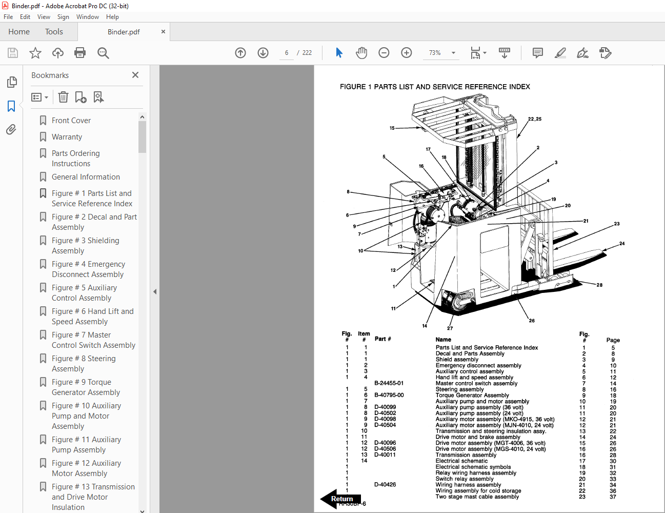
Figure # 1 Parts List and Service Reference Index 6
Figure # 2 Decal and Part Assembly 8
Figure # 3 Shielding Assembly 9
Figure # 4 Emergency Disconnect Assembly 10
Figure # 5 Auxiliary Control Assembly 11
Figure # 6 Hand Lift and Speed Assembly 12
Figure # 7 Master Control Switch Assembly 14
Figure # 8 Steering Assembly 16
Figure # 9 Torque Generator Assembly 18
Figure # 10 Auxiliary Pump and Motor Assembly 19
Figure # 11 Auxiliary Pump Assembly 20
Figure # 12 Auxiliary Motor Assembly 21
Figure # 13 Transmission and Drive Motor Insulation 22
Figure # 14 Drive Motor and Brake Assembly 24
Figure # 15 Drive Motor Assembly 26
Figure # 16 Transmission Assembly 28
Figure # 17 Electrical Schematic 30
Figure # 18 Electrical Schematic Symbols 31
Figure # 19 Relay Wiring Harness Assembly 32
Figure # 20 Switch Relay Assembly 33
Figure # 21 Wiring Harness Assembly 34
Figure # 22 Wiring Assembly for Cold Storage 36
Figure # 23 2 Stage Mast Cable Assembly 37
Figure # 24 3 Stage Mast Cable Assembly 38
Figure # 25 Reach Cable Assembly 39
Figure # 26 Power Component Wiring 40
Figure # 27 SCR and Contactor Panel Assembly 41
Figure # 28 EV-1 SCR Control 42
Figure # 29 Transformer Assembly 43
Figure # 30 Rectifier Heat Sink Assembly 44
Figure # 31 GE Contactor Assembly 45
Figure # 32 GE Contactor Assembly 46
Figure # 33 Contactor Assembly 47
Figure # 34 Connector Assembly 48
Figure # 35 Warning Light Assembly 49
Figure # 36 Hydraulic Schematic 50
Figure # 37 Hydraulic Schematic Symbols 51
Figure # 38 Auxiliary Pump and Reservoir Assembly 52
Figure # 39 Hydraulic Reservoir Assembly 53
Figure # 40 Lift Pump and Motor Assembly 54
Figure # 41 Lift Pump and Motor Assembly 55
Figure # 42 Lift Motor Assembly 56
Figure # 43 24 Volt Lift Pump Assembly 57
Figure # 44 36 Volt Lift Pump Assembly 58
Figure # 45 Lift Control Valve Assembly 59
Figure # 46 Torque Generator and Filter Assembly 60
Figure # 47 Tube and Hose Assembly 61
Figure # 48 Auxiliary Control Valve Assembly 62
Figure # 49 2 Stage Cylinder and Reservoir Assembly 63
Figure # 50 2 Stage Cylinder Assembly 64
Figure # 51 3 Stage Cylinders and Reservoir Assembly 66
Figure # 52 3 Stage Staging Cylinder Assembly 68
Figure # 53 3 Stage Freelift Cylinder Assembly 69
Figure # 54 2 Stage Mast Hydraulic Hose Assembly 70
Figure # 55 3 Stage Mast Hydraulic Hose Assembly 71
Figure # 56 Standard Reach Hose Assembly 72
Figure # 57 Flow Divider Assembly 73
Figure # 59 Reach with Tilt Hose Assembly 74
Figure # 60 Reach with Tilt Manifold Valve Assembly 75
Figure # 61 Sideshifter Hose Assembly 76
Figure # 62 Sideshifter Cylinder Assembly 77
Figure # 63 Sideshifter Manifold Valve Assembly 78
Figure # 64 Deep Reach Valve and Hose Assembly 79
Figure # 65 Deep Reach Reach Cylinder and Hose Assembly 80
Figure # 66 Deep Reach Manifold Valve Assembly 81
Figure # 67 Deep Reach, Reach Cylinder Assembly 82
Figure # 68 Deep Reach, Tilt Cylinder and Hose Assembly 83
Figure # 69 Deep Reach, Tilt Cylinder Assembly 84
Figure # 71 2 Stage Mast Insulation Assembly 85
Figure # 72 2 Stage Inner Column Assembly 86
Figure # 73 2 Stage Outer Column Assembly 87
Figure # 74 2 Stage Cylinder Assembly and Related Parts 88
Figure # 75 Single Reach Assembly 89
Figure # 76 Single Reach Standard Front Frame Assembly 90
Figure # 77 Single Reach Tilt Front Frame Assembly 91
Figure # 78 Deep Reach Assembly 92
Figure # 79 Sideshifter Assembly 93
Figure # 80 Fork Assembly 94
Figure # 81 3 Stage Mast Insulation Assembly 95
Figure # 82 3 Stage Outer Column Assembly 96
Figure # 83 3 Stage Intermediate Column Assembly 97
Figure # 84 3 Stage Inner Column Assembly 98
Figure # 85 3 Stage Freelift Cylinder Assembly and Related Parts 99
Figure # 86 Main Frame and Load Wheel Assembly100
Figure # 87 Caster Assembly104
Figure # 88 Single Load Wheel Assembly106
Figure # 89 4 Inch High Outriggers Articulating Load Wheel Assembly107
Figure # 90 Articulating Load Wheel Assembly108
Back Cover110
Front Cover111
Warranty112
Parts Ordering Instructions113
General Information115
Figure 1 Parts List and Service Reference Index116
Figure 2 Decal and Part Assembly118
Figure 3 Shielding Assembly119
Figure 4 Emergency Disconnect Assembly120
Figure 5 Auxiliary Control Assembly121
Figure 6 Hand Lift and Speed Assembly122
Figure 7 Master Control Switch Assembly124
Figure 8 Steering Assembly126
Figure 9 Torque Generator Assembly128
Figure 10 Auxiliary Pump and Motor Assembly129
Figure 11 Auxiliary Pump Assembly130
Figure 12 Auxiliary Motor Assembly131
Figure 13 Transmission and Drive Motor Insulation132
Figure 14 Drive Motor and Brake Assembly134
Figure 15 Drive Motor Assembly136
Figure 16 Transmission Assembly138
Figure 17 Electrical Schematic140
Figure 18 Electrical Schematic Symbols141
Figure 21 Wiring Harness Assembly144
Figure 22 Wiring Assembly for Cold Storage146
Figure 23 2 Stage Mast Cable Assembly147
Figure 24 3 Stage Mast Cable Assembly148
Figure 25 Reach Cable Assembly149
Figure 26 Power Component Wiring150
Figure 27 SCR and Contactor Panel Assembly151
Figure 28 EV-1 SCR Control152
Figure 29 Transformer Assembly153
Figure 30 Rectifier Heat Sink Assembly154
Figure 31 GE Contactor Assembly155
Figure 32 GE Contactor Assembly156
Figure 33 Contactor Assembly157
Figure 34 Connector Assembly158
Figure 35 Warning Light Assembly159
Figure 36 Hydraulic Schematic160
Figure 37 Hydraulic Schematic Symbols161
Figure 38 Auxiliary Pump and Reservoir Assembly162
Figure 39 Hydraulic Reservoir Assembly163
Figure 40 Lift Pump and Motor Assembly164
Figure 41 Lift Pump and Motor Assembly165
Figure 42 Lift Motor Assembly166
Figure 43 24 Volt Lift Pump Assembly167
Figure 44 36 Volt Lift Pump Assembly168
Figure 45 Lift Control Valve Assembly169
Figure 46 Torque Generator and Filter Assembly170
Figure 47 Tube and Hose Assembly171
Figure 48 Auxiliary Control Valve Assembly172
Figure 49 2 Stage Cylinder and Reservoir Assembly173
Figure 50 2 Stage Cylinder Assembly174
Figure 51 3 Stage Cylinders and Reservoir Assembly176
Figure 52 3 Stage Staging Cylinder Assembly178
Figure 53 3 Stage Freelift Cylinder Assembly179
Figure 54 2 Stage Mast Hydraulic Hose Assembly180
Figure 55 3 Stage Mast Hydraulic Hose Assembly181
Figure 56 Standard Reach Hose Assembly182
Figure 57 Flow Divider Assembly183
Figure 58 Reach and Tilt Cylinder Assembly184
Figure 59 Reach with Tilt Hose Assembly185
Figure 60 Reach with Tilt Manifold Valve Assembly186
Figure 61 Sideshifter Hose Assembly187
Figure 62 Sideshifter Cylinder Assembly188
Figure 63 Sideshifter Manifold Valve Assembly189
Figure 64 Deep Reach, Valve and Hose Assembly190
Figure 65 Deep Reach, Reach Cylinder and Hose Assembly191
Figure 66 Deep Reach, Manifold Valve Assembly192
Figure 67 Deep Reach, Reach Cylinder Assembly193
Figure 68 Deep Reach, Tilt Cylinder and Hose Assembly194
Figure 69 Deep Reach, Tilt Cylinder Assembly195
Figure 70 Deep Reach, Sideshifter Hose Assembly196
Figure 71 2 Stage Mast Insulation Assembly197
Figure 72 2 Stage Inner Column Assembly198
Figure 73 2 Stage Outer Column Assembly199
Figure 74 2 Stage Cylinder Assembly and Related Parts200
Figure 75 Single Reach Assembly201
Figure 76 Single Reach Standard Front Frame Assembly202
Figure 77 Single Reach Tilt Front Frame Assembly203
Figure 78 Deep Reach Assembly204
Figure 79 Sideshifter Assembly205
Figure 80 Fork Assembly206
Figure 81 3 Stage Mast Insulation Assembly207
Figure 82 3 Stage Outer Column Assembly208
Figure 83 3 Stage Intermediate Column Assembly209
Figure 84 3 Stage Inner Column Assembly210
Figure 85 3 Stage Freelift Cylinder Assembly and Related Parts211
Figure 86 Main Frame and Load Wheel Assembly212
Figure 87 Caster Assembly216
Figure 88 Single Load Wheel Assembly218
Figure 89 4 Inch High Outriggers Articulating Load Wheel Assembly219
Figure 90 Articulating Load Wheel Assembly220
Back Cover222
IMAGES PREVIEW OF THE MANUAL:
More products