$42
BT Forklift SN 20 30 40 Electric Walkie Straddle Stacker Truck Parts Manual – PDF DOWNLOAD
BT Forklift SN 20 30 40 Electric Walkie Straddle Stacker Truck Parts Manual – PDF DOWNLOAD
FILE DETAILS:
BT Forklift SN 20 30 40 Electric Walkie Straddle Stacker Truck Parts Manual – PDF DOWNLOAD
Language : English,
Pages :874
Downloadable : Yes
File Type : PDF
TABLE OF CONTENTS:
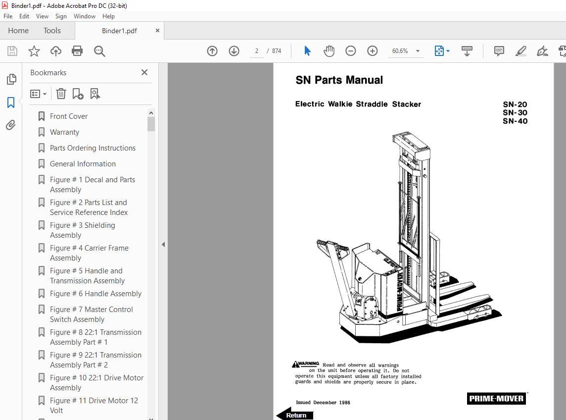
BT Forklift SN 20 30 40 Electric Walkie Straddle Stacker Truck Parts Manual – PDF DOWNLOAD
Front Cover 2
Warranty 3
Parts Ordering Instructions 4
General Information 5
Figure # 1 Decal and Parts Assembly 7
Figure # 2 Parts List and Service Reference Index 9
Figure # 3 Shielding Assembly 11
Figure # 4 Carrier Frame Assembly 13
Figure # 5 Handle and Transmission Assembly 15
Figure # 6 Handle Assembly 17
Figure # 7 Master Control Switch Assembly 19
Figure # 8 22:1 Transmission Assembly Part # 1 21
Figure # 9 22:1 Transmission Assembly Part # 2 23
Figure # 10 22:1 Drive Motor Assembly 25
Figure # 11 Drive Motor 12 Volt 27
Figure # 12 Drive Motor 24 Volt 29
Figure # 13 Electrical Schematic 31
Figure # 14 Electrical Schematic Symbols 32
Figure # 15 Control Wiring Harness 33
Figure # 16 12 Volt Power Component Wiring 35
Figure # 17 24 Volt Power Component Wiring 37
Figure # 18 Control Panel Assembly 39
Figure # 19 GE Contactor Assembly 41
Figure # 20 GE Contactor Assembly 43
Figure # 21 Power Connector Assembly 45
Figure # 22 Hydraulic Schematic 47
Figure # 23 Hydraulic Schematic Symbols 48
Figure # 24 12/24 Volt Hydraulic Assembly 49
Figure # 25 12/24 Volt Reservoir Pump and Motor 51
Figure # 26 12/24 Volt Pump and Motor Assembly 53
Figure # 27 Pump Motor Assembly 12 Volt and 24 Volt 55
Figure # 28 24 Volt Hydraulic Assembly 57
Figure # 29 24 Volt Reservoir Assembly 59
Figure # 30 24 Volt Pump and Motor Assembly 61
Figure # 31 Pump Assembly 63
Figure # 32 24 Volt Pump Assembly 65
Figure # 33 24 Volt Pump Motor Assembly 67
Figure # 34 24 Volt Pump Motor Assembly 69
Figure # 35 Lift Cylinder Assembly 71
Figure # 36 Manual Hydraulic Assembly 73
Figure # 37 Valve Mounting Assembly 75
Figure # 38 2 and 3 Spool Valve Assembly 77
Figure # 39 2 Stage Mast Installation Assembly 79
Figure # 40 2 Stage Inner Column Assembly 81
Figure # 41 2 Stage Cylinder Assembly and Related Parts 83
Figure # 42 2 Stage Standard Lift Frame and Load Backrest 85
Figure # 43 2 Stage ITA Lift Frame and Load Backrest 87
Figure # 44 Fork Assembly 89
Figure # 45 3 Stage Mast Installation Assembly 91
Figure # 46 3 Stage Outer Column Assembly 93
Figure # 47 3 Stage Intermediate Column Assembly 95
Figure # 48 3 Stage Inner Column Assembly 97
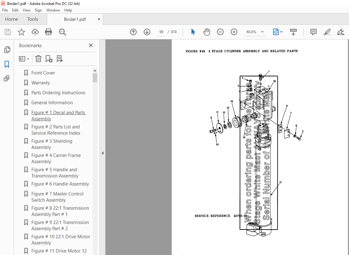
Figure # 49 3 Stage Cylinder Assembly and Related Parts 99
Figure # 50 3 Stage Cylinder Assembly101
Figure # 51 3 Stage Lift Frame and Load Backrest103
Figure # 52 Load Wheel Assembly105
Figure # 53 Spring Loaded Caster Assembly107
Figure # 54 Special Tools and Lubrications109
Numerical Index111
Back Cover121
Front Cover122
Parts Ordering Instructions123
General Information124
Figure # 01 Decals and Parts Assembly125
Figure # 02 Parts List Index127
Figure # 11 Transmission and Handle Assembly131
Figure # 12 Standard Control Handle Assembly133
Figure # 13 Thumb Control Handle Assembly135
Figure # 14 Transmission Assembly, Part # 1137
Figure # 15 Single Disc Brake Transmission Assembly139
Figure # 16 Drive Motor Assembly141
Figure # 21 Resistor Electrical Schematic142
Figure # 22 Resistor Electrical Schematic Symbols144
Figure # 23 Resistor Control Wiring Harness Assembly145
Figure # 24 Resistor Power Component Wiring147
Figure # 25 Control Panel Assembly149
Figure # 26 Second Speed Contactor Assembly151
Figure # 27 Forward & Rearward Contactor Assembly153
Figure # 28 Power Connector Assembly155
Figure # 29 Bosch Hydraulic Pump Motor Assembly157
Figure # 210 12 Volt Drive Motor Assembly159
Figure # 211 24 Volt Drive Motor Assembly161
Figure # 212 Pump Motor Assembly163
Figure # 213 Warning Light Assembly165
SN-20 Hydraulic Section168
Figure # 31 SN-20 Two Stage Hydraulic Schematic169
Figure # 32 SN-20 Two Stage Hydraulic Schematic Symbols170
Figure # 33 SN-20 12/24 Volt Two Stage Mast Hydraulic System171
Figure # 34 SN-20 12/24 Volt Reservoir and Pump Assembly173
Figure # 35 SN-20 Bosch Pump and Motor Assembly175
Figure # 36 SN-20 Lift Cylinder Assembly177
Figure # 37 SN-20 Three Stage Hydraulic Schematic179
Figure # 38 SN-20 Three Stage Hydraulic Schematic Symbols180
Figure # 39 SN-20 12/24 Volt Three Stage Mast Hydraulic System181
Figure # 310 SN-20 12/24 Volt Reservoir and Pump Assembly183
Figure # 311 SN-20 Bosch Pump and Motor Assembly185
Figure # 312 SN-20 Three Stage Freelift Cylinder Assembly187
Figure # 313 SN-20 Three Stage Freelift Cylinder Assembly189
SN-30 Hydraulic Section192
Figure # 314 SN-30 Two Stage Hydraulic Schematic193
Figure # 315 SN-30 Two Stage Hydraulic Schematic Symbols194
Figure # 316 SN-30 12 Volt Two Stage Mast Hydraulic System195
Figure # 317 SN-30 Hydraulic Pump and Valve Installation, 24 Volt197
Figure # 318 SN-30 12 Volt Reservoir and Pump Assembly199
Figure # 319 SN-30 Two Stage Mast Bosch Pump and Motor Assembly201
Figure # 320 SN-30 Two Stage Lift Cylinder Assembly203
Figure # 321 SN-30 Two Stage Hydraulic Reservoir Assembly205
Figure # 322 SN-30 24 Volt Lift Pump and Motor Assembly207
Figure # 323 SN-30 24 Volt Lift Pump Assembly209
Figure # 324 SN-30 Three Stage Hydraulic Schematic211
Figure # 326 SN-30 12 Volt Three Stage Mast Hydraulic System213
Figure # 327 SN-30 24 Volt Three Stage Hydraulic System, Part # 1215
Figure # 328 SN-30 24 Volt Three Stage Mast Hydraulic System, Part # 2217
Figure # 329 SN-30 12 Volt Reservoir and Pump Assembly219
Figure # 330 SN-30 Bosch Pump and Motor Assembly221
Figure # 331 SN-30 Three Stage Freelift Cylinder Assembly223
Figure # 332 SN-30 Three Stage Freelift Cylinder Assembly225
Figure # 333 SN-30 24 Volt Three Stage Hydraulic Reservoir Assembly227
Figure # 334 SN-30 24 Volt Lift Pump and Motor Assembly229
Figure # 335 SN-30 Lift Pump Assembly231
Figure # 336 SN-30 Manual Hydraulic Schematic233
Figure # 337 SN-30 Manual Hydraulic Schematic Symbols234
Figure # 338 SN-30 Manual Hydraulic System – Part # 1235
Figure # 339 SN-30 Manual Hydraulic System – Part # 2237
Figure # 340 SN-30 Manual Lift Two Stage Lift Cylinder and Related Parts239
Figure # 341 SN-30 Manual Lift Three Stage Lift Cylinders and Related Parts241
Figure # 342 SN-30 Manual Two/Three Spool Control Valve Assembly243
Figure # 343 SN-30 Manual Lift Pump and Motor Assembly245
Figure # 344 SN-30 Manual Lift Pump Assembly247
Figure # 345 SN-30 Manual Lift Hydraulic Reservoir Assembly249
Figure # 346 SN-30 Manual Lift Two Stage Cylinder Assembly251
Figure # 348 SN-30 Manual Lift Three Stage Freelift Cylinder Assembly255
Figure # 347 SN-30 Manual Lift Three Stage Freelift Cylinder Assembly253
SN-40 Hydraulic Section258
Figure # 349 SN-40 Two Stage Hydraulic Schematic259
Figure # 350 SN-40 Two Stage Hydraulic Schematic Symbols260
Figure # 351 SN-40 Two Stage Hydraulic System – Part # 1261
Figure # 352 SN-40 Two Stage Hydraulic System – Part # 2263
Figure # 353 SN-40 Two Stage Lift Cylinder and Related Parts265
Figure # 354 SN-40 Two/Three Spool Control Valve Assembly267
Figure # 355 SN-40 Lift Pump and Motor Assembly269
Figure # 356 SN-40 Lift Pump Assembly271
Figure # 357 SN-40 Hydraulic Reservoir Assembly273
Figure # 358 SN-40 Two Stage Lift Cylinder Assembly275
Figure # 359 SN-40 Three Stage Hydraulic Schematic277
Figure # 360 SN-40 Three Stage Hydraulic Schematic Symbols278
Figure # 361 SN-40 Three Stage Hydraulic System – Part # 1279
Figure # 362 SN-40 Three Stage Hydraulic System – Part # 2281
Figure # 363 SN-40 Three Stage Lift Cylinders and Related Parts283
Figure # 364 SN-40 Two/Three Spool Control Valve Assembly285
Figure # 365 SN-40 Lift Pump and Motor Assembly287
Figure # 366 SN-40 Lift Pump Assembly289
Figure # 367 SN-40 Hydraulic Reservoir Assembly291
Figure # 368 SN-40 Three Stage Staging Cylinder Assembly293
Figure # 369 SN-40 Three Stage Freelift Cylinder Assembly295
Figure # 41 Shielding Assembly297
Figure # 42 Main Frame and Load Wheel Installation299
Figure # 43 Caster Assembly301
Figure # 44 Two/Three Spool Control Valve Mounting Assembly303
Figure # 45 Pallet Centering Device305
Figure # 51 SN-20/30 Two Stage Mast Installation307
Figure # 52 SN-20/30 Two Stage Outer Column Assembly (Frame)309
Figure # 53 SN-20/30 Two Stage Inner Column Assembly311
Figure # 54 SN-20/30 Two Stage Mast Cylinder and Related Parts313
Figure # 55 SN-20/30 Two Stage Mast Lift Frame and Load Backrest Assembly315
Figure # 56 SN-20/30 Two Stage Fork Assembly317
Figure # 57 SN-20/30 Three Stage Mast Installation319
Figure # 58 SN-20/30 Three Stage Mast Outer Column Assembly321
Figure # 59 SN-20/30 Three Stage Mast Intermediate Column Assembly323
Figure # 510 SN-20/30 Three Stage Mast Inner Column Assembly325
Figure # 511 SN-20/30 Three Stage Mast Freelift Cylinder and Related Parts327
Figure # 512 SN-20/30 Three Stage Mast Lift Frame and Backrest Assembly329
Figure # 513 SN-20/30 Three Stage Fork Assembly331
Figure # 514 SN-40 Two Stage Mast Installation333
Figure # 515 SN-40 Two Stage Mast Outer Column Assembly335
Figure # 516 SN-40 Two Stage Mast Inner Column Assembly337
Figure # 517 SN-40 Two Stage Mast Cylinder and Related Parts339
Figure # 518 SN-40 Two Stage Mast Lift Frame and Load Backrest Assembly341
Figure # 519 SN-40 Two Stage Fork Assembly343
Figure # 520 SN-40 Three Stage Mast Installation345
Figure # 521 SN-40 Three Stage Mast Outer Column Assembly347
Figure # 522 SN-40 Three Stage Mast Intermediate Column Assembly349
Figure # 523 SN-40 Three Stage Mast Inner Column Assembly351
Figure # 524 SN-40 Three Stage Mast Freelift Cylinder Installation353
Figure # 525 SN-40 Three Stage Mast Lift Frame and Load Backrest Assembly355
Figure # 526 SN-40 Three Stage Fork Assembly357
Figure # 71 Special Tools and Lubrications359
Back Cover361
Front Cover362
Parts Ordering Instructions363
General Information364
Alphabetical Index365
Figure # 01 Decals and Parts Assembly369
Figure # 11 Transmission and Handle Assembly371
Figure # 12 Twist Grip Resistor & Transistor Control Handle Assembly373
Figure # 13 Thumb Control Resistor & Transistor Control Handle Assembly375
Figure # 14 Transmission Assembly, Part # 1377
Figure # 15 Transmission Assembly, Part # 2379
Figure # 16 Drive Motor Assembly381
Figure # 21 Resistor Electrical Schematic383
Figure # 22 Resistor Electrical Schematic Symbols384
Figure # 23 Resistor Control Wiring Harness Assembly385
Figure # 24 Resistor Power Component Wiring387
Figure # 25 Control Panel Assembly389
Figure # 26 Second Speed Contactor Assembly391
Figure # 27 Forward & Rearward Contactor Assembly393
Figure # 28 Power Connector Assembly395
Figure # 29 Bosch Hydraulic Pump Motor Assembly397
Figure # 210 12 Volt Drive Motor Assembly399
Figure # 211 24 Volt Drive Motor Assembly401
Figure # 212 Pump Motor Assembly403
Figure # 213 Warning Light Assembly405
Figure # 214 Transistor Electrical Schematic407
Figure # 215 Transistor Electrical Schematic Symbols408
Figure # 216 Transistor Control Wiring Harness Assembly409
Figure # 217 Control Wiring Harness411
Figure # 218 Control Panel Assembly413
SN-20 Hydraulic Section416
Figure # 31 SN-20 Two Stage Hydraulic Schematic417
Figure # 32 SN-20 Two Stage Hydraulic Schematic Symbols418
Figure # 33 SN-20 12/24 Volt Two Stage Mast Hydraulic System419
Figure # 34 SN-20 12/24 Volt Reservoir and Pump Assembly421
Figure # 35 SN-20 Bosch Pump and Motor Assembly423
Figure # 36 SN-20 Lift Cylinder Assembly425
Figure # 37 SN-20 Three Stage Hydraulic Schematic427
Figure # 38 SN-20 Three Stage Hydraulic Schematic Symbols428
Figure # 39 SN-20 12/24 Volt Three Stage Mast Hydraulic System429
Figure # 310 SN-20 12/24 Volt Reservoir and Pump Assembly431
Figure # 311 SN-20 Bosch Pump and Motor Assembly433
Figure # 312 SN-20 Three Stage Freelift Cylinder Assembly435
Figure # 313 SN-20 Three Stage Freelift Cylinder Assembly437
SN-30 Hydraulic Section440
Figure # 314 SN-30 Two Stage Hydraulic Schematic441
Figure # 315 SN-30 Two Stage Hydraulic Schematic Symbols442
Figure # 316 SN-30 12 Volt Two Stage Mast Hydraulic System443
Figure # 317 SN-30 Hydraulic Pump and Valve Installation, 24 Volt445
Figure # 318 SN-30 12 Volt Reservoir and Pump Assembly447
Figure # 319 SN-30 Two Stage Mast Bosch Pump and Motor Assembly449
Figure # 320 SN-30 Two Stage Lift Cylinder Assembly451
Figure # 321 SN-30 Two Stage Hydraulic Reservoir Assembly453
Figure # 322 SN-30 24 Volt Lift Pump and Motor Assembly455
Figure # 323 SN-30 24 Volt Lift Pump Assembly457
Figure # 324 SN-30 Three Stage Hydraulic Schematic459
Figure # 325 SN-30 Three Stage Hydraulic Schematic Symbols460
Figure # 326 SN-30 12 Volt Three Stage Mast Hydraulic System461
Figure # 327 SN-30 24 Volt Three Stage Hydraulic System, Part # 1463
Figure # 328 SN-30 24 Volt Three Stage Mast Hydraulic System, Part # 2465
Figure # 329 SN-30 12 Volt Reservoir and Pump Assembly467
Figure # 330 SN-30 Bosch Pump and Motor Assembly469
Figure # 331 SN-30 Three Stage Freelift Cylinder Assembly471
Figure # 332 SN-30 Three Stage Freelift Cylinder Assembly473
Figure # 333 SN-30 24 Volt Three Stage Hydraulic Reservoir Assembly475
Figure # 334 SN-30 24 Volt Lift Pump and Motor Assembly477
Figure # 335 SN-30 Lift Pump Assembly479
Figure # 336 SN-30 Manual Hydraulic Schematic481
Figure # 337 SN-30 Manual Hydraulic Schematic Symbols482
Figure # 338 SN-30 Manual Hydraulic System – Part # 1483
Figure # 339 SN-30 Manual Hydraulic System – Part # 2485
Figure # 340 SN-30 Manual Lift, Two Stage Lift Cylinder and Related Parts487
Figure # 341 SN-30 Manual Lift, Three Stage Lift Cylinders and Related Parts489
Figure # 342 SN-30 Manual Two/Three Spool Control Valve Assembly491
Figure # 343 SN-30 Manual Lift Pump and Motor Assembly493
Figure # 344 SN-30 Manual Lift Pump Assembly495
Figure # 345 SN-30 Manual Lift Hydraulic Reservoir Assembly497
Figure # 346 SN-30 Manual Lift, Two Stage Cylinder Assembly499
Figure # 347 SN-30 Manual Lift Three Stage Freelift Cylinder Assembly501
Figure # 348 SN-30 Manual Lift Three Stage Freelift Cylinder Assembly503
SN-40 Hydraulic Section506
Figure # 349 SN-40 Two Stage Hydraulic Schematic507
Figure # 350 SN-40 Two Stage Hydraulic Schematic Symbols508
Figure # 351 SN-40 Two Stage Hydraulic System – Part # 1509
Figure # 352 SN-40 Two Stage Hydraulic System – Part # 2511
Figure # 353 SN-40 Two Stage Lift Cylinder and Related Parts513
Figure # 354 SN-40 Two/Three Spool Control Valve Assembly515
Figure # 355 SN-40 Lift Pump and Motor Assembly517
Figure # 356 SN-40 Lift Pump Assembly519
Figure # 357 SN-40 Hydraulic Reservoir Assembly521
Figure # 358 SN-40 Two Stage Lift Cylinder Assembly523
Figure # 359 SN-40 Three Stage Hydraulic Schematic525
Figure # 360 SN-40 Three Stage Hydraulic Schematic Symbols526
Figure # 361 SN-40 Three Stage Hydraulic System – Part # 1527
Figure # 362 SN-40 Three Stage Hydraulic System – Part # 2529
Figure # 363 SN-40 Three Stage Lift Cylinders and Related Parts531
Figure # 364 SN-40 Two/Three Spool Control Valve Assembly533
Figure # 365 SN-40 Lift Pump and Motor Assembly535
Figure # 366 SN-40 Lift Pump Assembly537
Figure # 367 SN-40 Hydraulic Reservoir Assembly539
Figure # 368 SN-40 Three Stage Staging Cylinder Assembly541
Figure # 369 SN-40 Three Stage Freelift Cylinder Assembly543
Figure # 41 Shielding Assembly545
Figure # 42 Main Frame and Load Wheel Installation547
Figure # 43 Caster Assembly549
Figure # 44 Two/Three Spool Control Valve Mounting Assembly551
Figure # 45 Pallet Centering Device553
Figure # 51 SN-20/30 Two Stage Mast Installation555
Figure # 52 SN-20/30 Two Stage Outer Column Assembly (Frame)557
Figure # 53 SN-20/30 Two Stage Inner Column Assembly559
Figure # 54 SN-20/30 Two Stage Mast Cylinder and Related Parts561
Figure # 55 SN-20/30 Two Stage Mast Lift Frame and Load Backrest Assembly563
Figure # 56 SN-20/30 Two Stage Fork Assembly565
Figure # 57 SN-20/30 Three Stage Mast Installation567
Figure # 58 SN-20/30 Three Stage Mast Outer Column Assembly569
Figure # 59 SN-20/30 Three Stage Mast Intermediate Column Assembly571
Figure # 510 SN-20/30 Three Stage Mast Inner Column Assembly573
Figure # 511 SN-20/30 Three Stage Mast Freelift Cylinder and Related Parts575
Figure # 512 SN-20/30 Three Stage Mast Lift Frame and Backrest Assembly577
Figure # 513 SN-20/30 Three Stage Fork Assembly579
Figure # 514 SN-40 Two Stage Mast Installation581
Figure # 515 SN-40 Two Stage Mast Outer Column Assembly583
Figure # 516 SN-40 Two Stage Mast Inner Column Assembly585
Figure # 517 SN-40 Two Stage Mast Cylinder and Related Parts587
Figure # 518 SN-40 Two Stage Mast Lift Frame and Load Backrest Assembly589
Figure # 519 SN-40 Two Stage Fork Assembly591
Figure # 520 SN-40 Three Stage Mast Installation593
Figure # 521 SN-40 Three Stage Mast Outer Column Assembly595
Figure # 522 SN-40 Three Stage Mast Intermediate Column Assembly597
Figure # 523 SN-40 Three Stage Mast Inner Column Assembly599
Figure # 524 SN-40 Three Stage Mast Freelift Cylinder Installation601
Figure # 525 SN-40 Three Stage Mast Lift Frame and Load Backrest Assembly603
Figure # 526 SN-40 Three Stage Fork Assembly605
Figure # 101 Special Tools and Lubrications607
Numerical Index610
Back Cover631
Front Cover632
Parts Ordering Instructions633
General Information634
Alphabetical Index635
Figure # 01 Decals and Parts Assembly639
Figure # 11 Transmission and Handle Assembly641
Figure # 12 Twist Grip Resistor & Transistor Control Handle Assembly643
Figure # 13 Thumb Control Resistor & Transistor Control Handle Assembly645
Figure # 14 Transmission Assembly, Part # I647
Figure # 15 Transmission Assembly, Part # II649
Figure # 16 Drive Motor Assembly651
Figure # 21 Resistor Electrical Schematic653
Figure # 22 Resistor Electrical Schematic Symbols654
Figure # 23 Resistor Control Wiring Harness Assembly655
Figure # 24 Resistor Power Component Wiring657
Figure # 25 Resistor Control Panel Assembly659
Figure # 26 Resistor Second Speed Contactor Assembly661
Figure # 27 Resistor Forward & Rearward Contactor Assembly663
Figure # 28 Power Connector Assembly665
Figure # 29 Hydraulic Pump Motor Assembly667
Figure # 210 Pump Motor Assembly669
Figure # 211 Drive Motor Assembly, 12 Volt671
Figure # 212 24 Volt Drive Motor Assembly673
Figure # 213 Warning Light Assembly675
Figure # 214 Transistor Electrical Schematic “E”677
Figure # 215 Transistor Electrical Schematic Symbols “E”678
Figure # 216 Transistor Control Wiring Harness “E”679
Figure # 217 Transistor Power Component Wiring “E”681
Figure # 218 Transistor Control Panel Assembly “E”683
Figure # 219 Transistor Forward & Rearward Contactor Assembly685
Figure # 220 Transistor Electrical Schematic “EE”687
Figure # 221 Transistor Electrical Schematic Symbols “EE”688
Figure # 222 Transistor Control Wiring Harness “EE”689
Figure # 223 Transistor Power Component Wiring “EE”691
Figure # 224 Transistor Control Panel Assembly “EE”693
SN-20 Hydraulic Section696
Figure # 31 SN-20 Two Stage Hydraulic Schematic697
Figure # 32 SN-20 Two Stage Hydraulic Schematic Symbols698
Figure # 33 SN-20 Two Stage Mast Hydraulic System699
Figure # 34 SN-20 Reservoir and Pump Assembly701
Figure # 35 SN-20 Pump and Motor Assembly703
Figure # 36 SN-20 Two Stage Lift Cylinder Assembly705
Figure # 37 SN-20 Three Stage Hydraulic Schematic707
Figure # 38 SN-20 Three Stage Hydraulic Schematic Symbols708
Figure # 39 SN-20 Three Stage Mast Hydraulic System709
Figure # 310 SN-20 Three Stage Freelift Cylinder Assembly711
Figure # 311 SN-20 Three Stage Staging Cylinder Assembly713
SN-30 Hydraulic Section716
Figure # 312 SN-30 Two Stage Hydraulic Schematic717
Figure # 313 SN-30 Two Stage Hydraulic Schematic Symbols718
Figure # 314 SN-30 Two Stage Mast Hydraulic System, 12 Volt719
Figure # 315 SN-30 Two Stage Mast Hydraulic System, 24 Volt721
Figure # 316 SN-30 Reservoir and Pump Assembly723
Figure # 317 SN-30 Pump and Motor Assembly725
Figure # 318 SN-30 Two Stage Lift Cylinder Assembly727
Figure # 319 SN-30 Two Stage Hydraulic Reservoir Assembly729
Figure # 320 Lift Pump and Motor Assembly731
Figure # 321 Lift Pump Assembly733
Figure # 322 SN-30 Three Stage Hydraulic Schematic735
Figure # 323 SN-30 Three Stage Hydraulic Schematic Symbols736
Figure # 324 SN-30 Three Stage Mast Hydraulic System, 12 Volt737
Figure # 325 SN-30 Three Stage Mast Hydraulic System, 24 Volt Part # I739
Figure # 326 SN-30 Three Stage Mast Hydraulic System, 24 Volt Part # II741
Figure # 327 SN-30 Three Stage Freelift Cylinder Assembly743
Figure # 328 SN-30 Three Stage Staging Cylinder Assembly745
Figure # 329 SN-30 Manual Control Hydraulic Schematic747
Figure # 330 SN-30 Manual Control Hydraulic Schematic Symbols748
Figure # 331 SN-30 Manual Control Hydraulic System – Part # I749
Figure # 332 SN-30 Manual Control Hydraulic System – Part # II751
Figure # 333 SN-30 Manual Lift, Two Stage Lift Cylinder and Related Part753
Figure # 334 SN-30 Manual Lift, Three Stage Lift Cylinder and Related Part755
Figure # 335 Two & Three Spool Control Valve Assembly757
SN-40 Hydraulic Section760
Figure # 336 SN-40 Two Stage Hydraulic Schematic761
Figure # 337 SN-40 Two Stage Hydraulic Schematic Symbols762
Figure # 338 SN-40 Manual Control Hydraulic System – Part # I763
Figure # 339 SN-40 Manual Control Hydraulic System – Part # II765
Figure # 340 SN-40 Manual Lift, Two Stage Lift Cylinder and Related Part767
Figure # 341 SN-40 Two Stage Cylinder Assembly769
Figure # 342 SN-40 Manual Control Hydraulic Schematic771
Figure # 343 SN-40 Manual Control Hydraulic Schematic Symbols772
Figure # 344 SN-40 Three Stage Hydraulic System – Part # I773
Figure # 345 SN-40 Three Stage Hydraulic System – Part # II775
Figure # 346 SN-40 Three Stage Lift Cylinder and Related Parts777
Figure # 347 SN-40 Three Stage Staging Cylinder Assembly779
Figure # 348 SN-40 Three Stage Freelift Cylinder Assembly781
Figure # 41 Shielding Assembly783
Figure # 42 Main Frame and Load Wheel Installation785
Figure # 43 Spring Loaded Caster Assembly787
Figure # 44 Control Valve Mounting Assembly789
Figure # 45 Pallet Centering Device791
Figure # 51 SN-20/30 Two Stage Mast Installation793
Figure # 52 SN-20/30 Two Stage Mast Outer Column Assembly (Frame)795
Figure # 53 SN-20/30 Two Stage Mast Inner Column Assembly797
Figure # 54 SN-20/30 Two Stage Mast Cylinder and Related Parts799
Figure # 55 SN-20/30 Two Stage Mast Lift Frame and Backrest Assembly801
Figure # 56 SN-20/30 Two Stage Fork Assembly803
Figure # 57 SN-20/30 Three Stage Mast Installation805
Figure # 58 SN-20/30 Three Stage Mast Outer Column Assembly (Frame)807
Figure # 59 SN-20/30 Three Stage Mast Intermediate Column Assembly809
Figure # 510 SN-20/30 Three Stage Mast Inner Column Assembly811
Figure # 511 SN-20/30 Three Stage Mast Freelift Cylinder and Related Parts813
Figure # 512 SN-20/30 Three Stage Mast Lift Frame and Backrest Assembly815
Figure # 513 SN-20/30 Three Stage Fork Assembly817
Figure # 514 SN-40 Two Stage Mast Installation819
Figure # 515 SN-40 Two Stage Mast Outer Column Assembly (Frame)821
Figure # 516 SN-40 Two Stage Mast Inner Column Assembly823
Figure # 517 SN-40 Two Stage Mast Cylinder and Related Parts825
Figure # 518 SN-40 Two Stage Mast Lift Frame and Backrest Assembly827
Figure # 519 SN-40 Two Stage Fork Assembly829
Figure # 520 SN-40 Three Stage Mast Installation831
Figure # 521 SN-40 Three Stage Mast Outer Column Assembly833
Figure # 522 SN-40 Three Stage Mast Intermediate Column Assembly835
Figure # 523 SN-40 Three Stage Mast Inner Column Assembly837
Figure # 524 SN-40 Three Stage Mast Freelift Cylinder Installation839
Figure # 525 SN-40 Three Stage Mast Lift Frame and Load Backrest Assembly841
Figure # 526 SN-40 Three Stage Fork Assembly843
Figure # 61 Hose Reel and Related Parts844
Figure # 62 Dual Elbow Swivel Assembly846
Figure # 63 Hose Reel Assembly848
Figure # 101 Special Tools and Lubrications850
Numerical Index853
Back Cover874
IMAGES PREVIEW OF THE MANUAL:
More products