Starting from:
$37
BT FORKLIFT SWE100,120,120S,120L,140,140L,200D Repair Manual – PDF DOWNLOAD
BT FORKLIFT SWE100,120,120S,120L,140,140L,200D Repair Manual – PDF DOWNLOAD
FILE DETAILS:
BT FORKLIFT SWE100,120,120S,120L,140,140L,200D Repair Manual – PDF DOWNLOAD
Language : English
Pages : 246
Downloadable : Yes
File Type : PDF
IMAGES PREVIEW OF THE MANUAL:
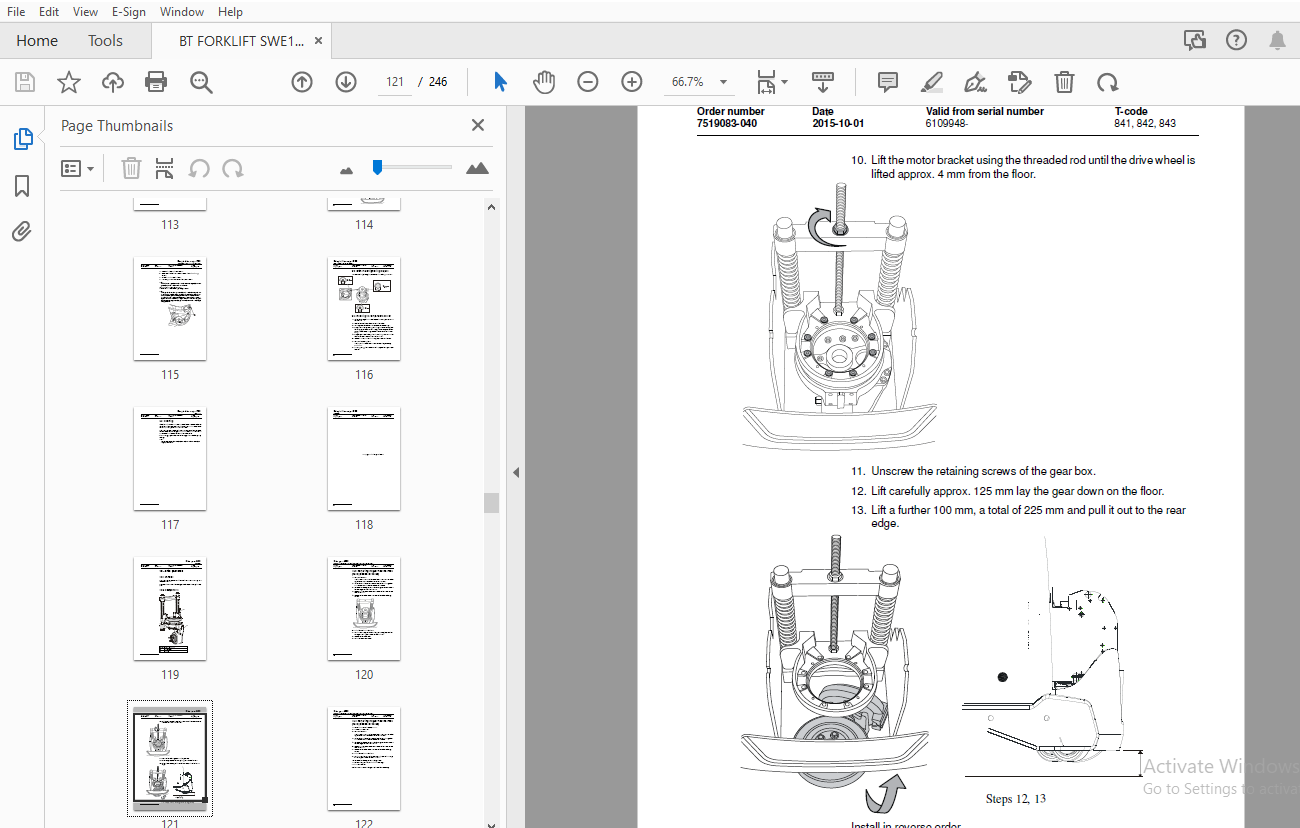
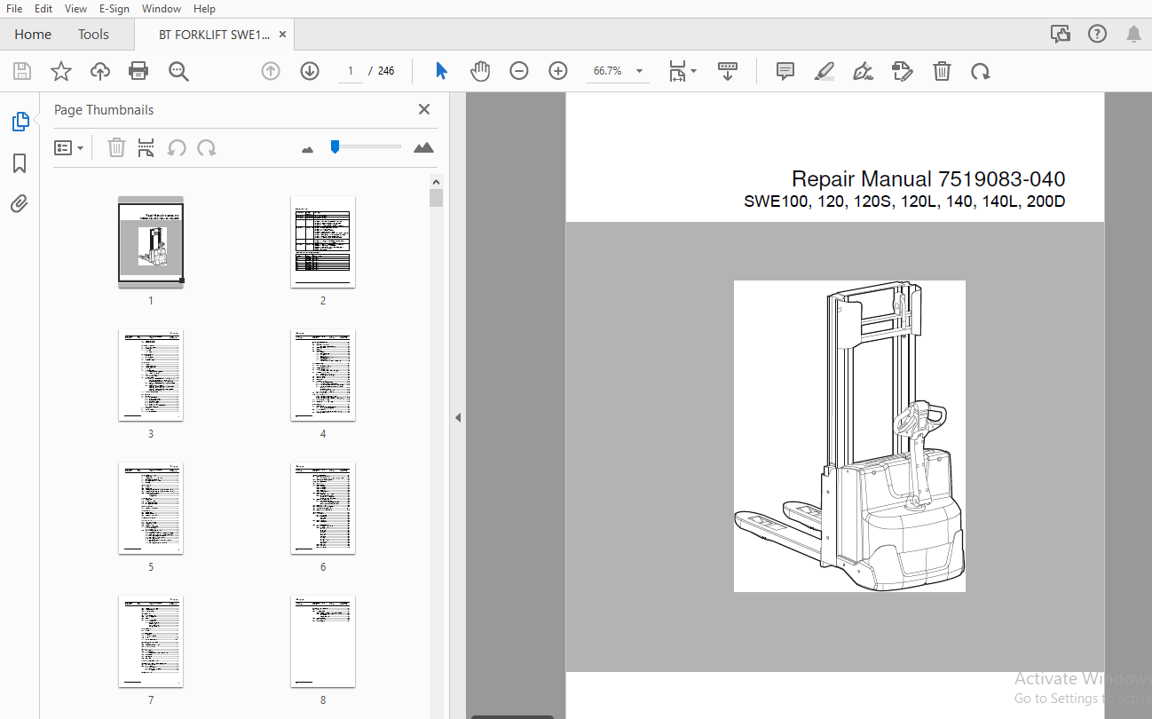
TABLE OF CONTENTS:
BT FORKLIFT SWE100,120,120S,120L,140,140L,200D Repair Manual – PDF DOWNLOAD
1 – Contents.........................................................................................0
2 – General introduction.............................................................................0
	2.1 How to use this manual.......................................................................0
	2.2 Warning symbols..............................................................................0
	2.3 Pictograms...................................................................................0
		2.3.1 Screws/Nuts............................................................................0
3 – General safety rules.............................................................................0
	3.1 Work safety..................................................................................0
	3.2 Electrical system............................................................................0
	3.3 Safe lifting.................................................................................0
	3.4 Truck modifications..........................................................................0
4 – Installation.....................................................................................0
	4.1 General......................................................................................0
	4.2 Transporting the truck.......................................................................0
	4.3 Transporting the mast........................................................................0
	4.4 Safe lifting.................................................................................0
	4.5 Battery installation.........................................................................0
		4.5.1 Safety when handling batteries.........................................................0
		4.5.2 Installing the battery.................................................................0
	4.6 Programming PIN codes........................................................................0
		4.6.1 PIN code standard......................................................................0
	4.7 Setting parameters...........................................................................0
		4.7.1 Setting the parameters for collision sensor (option)...................................0
			Collision sensor parameters 105, 106 and 111.............................................0
			Programming the PIN code for resetting the truck.........................................0
		4.7.2 Setting the parameters for the battery and the battery charger.........................0
		4.7.3 Parameter 107 – Battery size...........................................................0
			Verifying the parameter setting for freely ventilated batteries (Lead-acid batteries)....0
			Verifying the parameter setting for valve-regulated batteries (Hawker/Exide).............0
	4.8 Function and safety checks...................................................................0
5 – Maintenance......................................................................................0
	5.1 Introduction.................................................................................0
	5.2 Maintenance instructions.....................................................................0
		5.2.1 Cleaning and washing...................................................................0
		5.2.2 High-pressure washers..................................................................0
		5.2.3 Degreasing agents......................................................................0
		5.2.4 Cleaning the exterior..................................................................0
		5.2.5 Cleaning the chain.....................................................................0
		5.2.6 Cleaning the motor compartment.........................................................0
		5.2.7 Electric components....................................................................0
	5.3 General......................................................................................0
	5.4 Service intervals............................................................................0
	5.5 Maintenance schedule.........................................................................0
6 – Function and parameters..........................................................................0
	6.1 General......................................................................................0
	6.2 Description of the function..................................................................0
		Symbols on keypad and display................................................................0
	6.3 Operating principle..........................................................................0
	6.4 Hour meter...................................................................................0
	6.5 Parameters...................................................................................0
		6.5.1 General................................................................................0
		6.5.2 Displaying parameters..................................................................0
		6.5.3 Setting parameters.....................................................................0
		6.5.4 Operator parameters....................................................................0
			Factory preset operator parameters.......................................................0
		6.5.5 Service parameters.....................................................................0
		6.5.6 Factory parameters.....................................................................0
			* Matrix for hardware/software compatibility.............................................0
7 – Troubleshooting..................................................................................0
	7.1 General......................................................................................0
		Software compatibility.......................................................................0
	7.2 Emergency driving mode.......................................................................0
	7.3 Towing a defective truck.....................................................................0
		Tow using a tow truck and tow wagon:.........................................................0
	7.4 Troubleshooting methods......................................................................0
		7.4.1 General initial troubleshooting........................................................0
		7.4.2 Concluding troubleshooting.............................................................0
	7.5 Error code history...........................................................................0
	7.6 Error code system............................................................................0
	7.7 Error codes..................................................................................0
	7.8 Troubleshooting chart........................................................................0
		7.8.1 The truck cannot be driven.............................................................0
		7.8.2 Truck only travels at reduced speed....................................................0
		7.8.3 The truck can be driven but behaves abnormally.........................................0
		7.8.4 The truck can be driven, but some functions do not work................................0
			Software compatibility...................................................................0
			Hardware compatibility matrix............................................................0
		7.8.5 Defective hydraulic functions..........................................................0
	7.9 Built-in test function.......................................................................0
	7.10 Digital input/output status.................................................................0
		7.10.1 Test function “9” – Transistor regulator..............................................0
		7.10.2 Test function “10” – Logic card.......................................................0
		7.10.3 Test function “12” – Expansion unit SEU (option)......................................0
	7.11 Test function for the display...............................................................0
	7.12 Checking the built-in battery charger.......................................................0
8 – Chassis 0000.....................................................................................0
	8.1 Support arm 0350.............................................................................0
		8.1.1 Support arm lift, lateral adjustment...................................................0
		8.1.2 Adjusting the kneeling action..........................................................0
	8.2 Motor mounts 0450............................................................................0
		8.2.1 Replacing springs (not applicable for S212S)...........................................0
	8.3 Removing the platform........................................................................0
9 – Electric drive motor 1700........................................................................0
	9.1 Components...................................................................................0
	9.2 Removing the motor from the truck............................................................0
	9.3 Drive motor tightening torques...............................................................0
	9.4 Installing the temperature sensor............................................................0
	9.5 Cleaning.....................................................................................0
10 – Drive gear 2550.................................................................................0
	10.1 General.....................................................................................0
	10.2 Components..................................................................................0
	10.3 Removing the gear from the truck (not applicable for S212S).................................0
	10.4 Removing the gear from the truck (not applicable for S212S).................................0
	10.5 Replacing the wheel hub seal................................................................0
		Removing the seal............................................................................0
		Fitting the seal.............................................................................0
11 – Brakes 3180.....................................................................................0
	11.1 Components..................................................................................0
	11.2 Releasing the brake.........................................................................0
	11.3 Installing the dust shield..................................................................0
	11.4 Installing the dust shield..................................................................0
12 – Drive wheel 3530................................................................................0
	12.1 Replacing the drive wheel...................................................................0
13 – Castor wheels 3540..............................................................................0
	13.1 Components..................................................................................0
	13.2 Castor wheel mounting.......................................................................0
	13.3 Replacing the castor wheel..................................................................0
14 – Support arm wheel 3550..........................................................................0
15 – Tiller arm 4000.................................................................................0
	15.1 Tiller arm components.......................................................................0
	15.2 Removing the tiller arm.....................................................................0
	15.3 Replacing the gas spring....................................................................0
	15.4 Replacing the safety sensor.................................................................0
		15.4.1 Dismantling...........................................................................0
		15.4.2 Fitting...............................................................................0
	15.5 Electrical steering system – 4000...........................................................0
		15.5.1 Tiller arm handle C4110...............................................................0
		15.5.2 Components of the tiller arm handle (new design)......................................0
		15.5.3 Components of the tiller arm handle (old design)......................................0
		15.5.5 Replacing the signal button/switch....................................................0
		15.5.6 Replacement of lift/lower button......................................................0
		15.5.7 Replacing the button..................................................................0
		15.5.8 Changing the position of the controls - support arm lift/fork lift....................0
		15.5.9 Replacing the safety reversal switch..................................................0
16 – Electric components.............................................................................0
	16.1 Replacing the wiring harness................................................................0
		16.1.1 Replacing the transistor regulator wiring harness.....................................0
	16.2 Replacing the transistor regulator..........................................................0
17 – Hydraulic system 6000...........................................................................0
	17.1 General.....................................................................................0
	17.2 Hydraulic hygiene...........................................................................0
		17.2.1 Washing...............................................................................0
		17.2.2 Packaging.............................................................................0
		17.2.3 Handling..............................................................................0
		17.2.4 Storage...............................................................................0
		17.2.5 Work procedures.......................................................................0
	17.3 Hydraulic unit 6100.........................................................................0
		17.3.1 Emptying the hydraulic tank...........................................................0
		17.3.2 Hydraulic system, bleeding............................................................0
			Cylinders with bleeding valve............................................................0
			Cylinders without bleeding valve.........................................................0
	17.4 Hydraulic connections 6230..................................................................0
		17.4.1 Quick change connector................................................................0
			Connecting the quick change connector....................................................0
			Dismantling the quick change connector...................................................0
	17.5 Hydraulic calibration.......................................................................0
	17.6 Adjusting the pressure limiting valve.......................................................0
	17.7 Disassembling the hydraulic unit............................................................0
	17.8 Hydraulic unit tightening torques...........................................................0
18 – Lift mast – 7000................................................................................0
	18.1 Main mast 7100..............................................................................0
		18.1.1 Components............................................................................0
		18.1.2 Maintenance...........................................................................0
			Fixing point.............................................................................0
			Lubrication..............................................................................0
	18.2 Fork carriage 7420..........................................................................0
		18.2.1 Maintenance...........................................................................0
	18.3 Main lift chain system 7120.................................................................0
		18.3.1 Checking the chain setting............................................................0
		18.3.2 Checking the chain....................................................................0
			Noise....................................................................................0
			Surface rust.............................................................................0
			Rusty links..............................................................................0
			Stiff links..............................................................................0
			Bolt rotation............................................................................0
			Loose bolts..............................................................................0
			Outline wear.............................................................................0
			Stretching...............................................................................0
			Damage...................................................................................0
			Damaged plates...........................................................................0
			Damaged bolts............................................................................0
			Dirty chain..............................................................................0
		18.3.3 Cleaning..............................................................................0
		18.3.4 Lubrication...........................................................................0
		18.3.5 Adjustment............................................................................0
	18.4 Replacing the fork carriage.................................................................0
	18.5 Replacement of the mast.....................................................................0
	18.6 Adjusting the mast..........................................................................0
19 – Accessories.....................................................................................0
	19.1 Spider expansion unit.......................................................................0
	19.2 TLS - Truck log system......................................................................0
	19.3 ID unit.....................................................................................0
	19.4 Built-in battery charger....................................................................0
		19.4.1 Technical data........................................................................0
		19.4.2 Charging the battery..................................................................0
			Main charging............................................................................0
			Equalising charging......................................................................0
			Charging completed.......................................................................0
20 – Attachments.....................................................................................0
	20.1 General.....................................................................................0
21 – Technical data..................................................................................0
	21.1 S210, S212, S214............................................................................0
	21.2 S212L, S214L, S220D.........................................................................0
	21.3 S212S.......................................................................................0
	21.4 Overflow pressure for mast..................................................................0
22 – General tightening torques......................................................................0
	22.1 General.....................................................................................0
	22.2 Galvanised, non-oiled screws................................................................0
	22.3 Untreated, oiled bolts......................................................................0
23 – Tools...........................................................................................0
	23.1 MQS contacts................................................................................0
	23.2 AMP connectors..............................................................................0
		23.2.1 AMP connectors, Multilock series 040..................................................0
	23.3 Molex connectors............................................................................0
	23.4 Grease guns.................................................................................0
	23.5 Other tools.................................................................................0
24 – Oil and grease specification....................................................................0
25 – Electrical components and wiring diagram........................................................0
	25.1 Electric components.........................................................................0
	25.2 Wiring diagram..............................................................................0
		25.2.1 List of symbols.......................................................................0
		25.2.2 General wiring diagram................................................................0
		25.2.3 Wiring diagram........................................................................0
26 – Hydraulics chart................................................................................0
27 – Instructions for disposal.......................................................................0
	27.1 General.....................................................................................0
	27.2 Marking of plastics.........................................................................0
		27.2.1 General marking of products and packaging.............................................0
		27.2.2 Marking according to standard.........................................................0
			Abbreviations............................................................................0
			Marking examples.........................................................................0
	27.3 Pressure vessels............................................................................0
		27.3.1 Gas struts............................................................................0
	27.4 Sorting categories..........................................................................0
1 file (20.1MB)

