Starting from:
$41
BT Forklift SWE140S SWE145 SWE145L SWE160 SWE160L SWE200 SWE200L Repair Manual
BT Forklift SWE140S SWE145 SWE145L SWE160 SWE160L SWE200 SWE200L Repair Manual – PDF DOWNLOAD
FILE DETAILS:
BT Forklift SWE140S SWE145 SWE145L SWE160 SWE160L SWE200 SWE200L Repair Manual – PDF DOWNLOAD
Language : English
Pages : 532
Downloadable : Yes
File Type : PDF
IMAGES PREVIEW OF THE MANUAL:
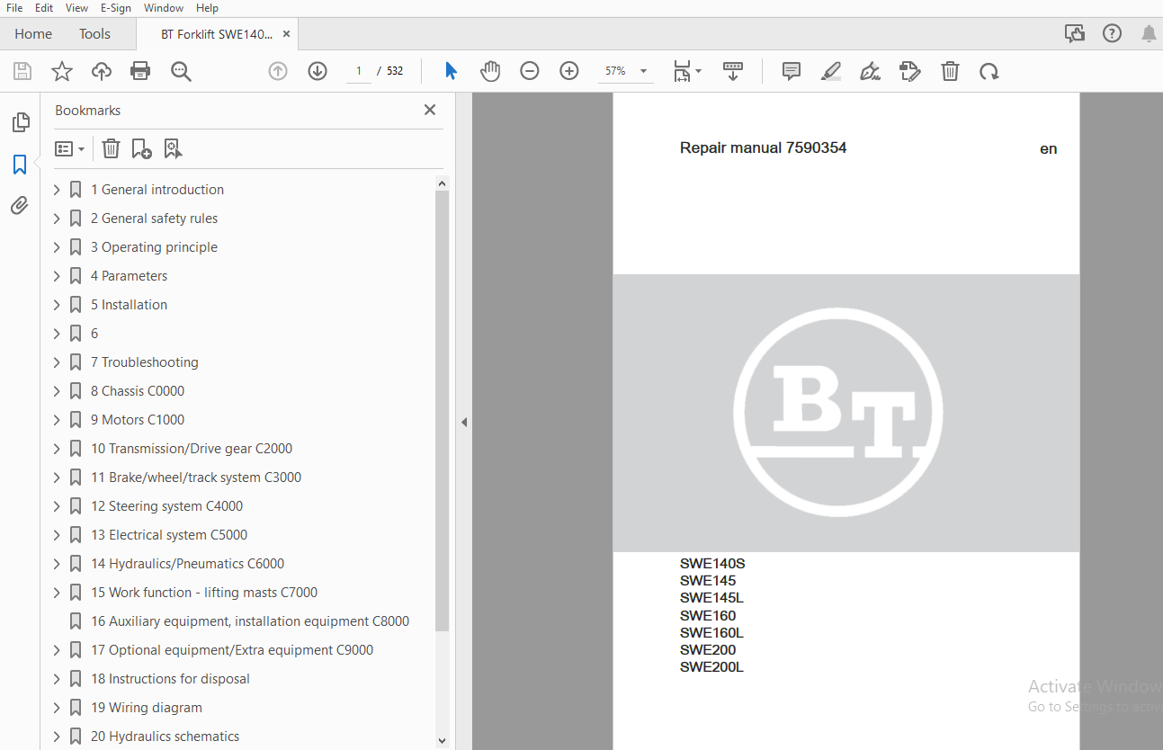
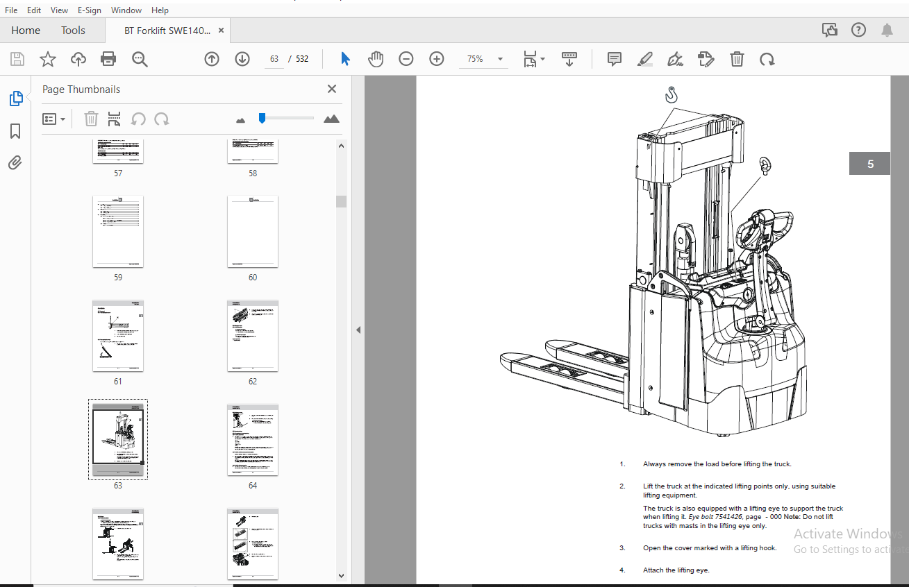
TABLE OF CONTENTS:
BT Forklift SWE140S SWE145 SWE145L SWE160 SWE160L SWE200 SWE200L Repair Manual – PDF DOWNLOAD
1 General introduction.................................................................................  9
	1.1 How to use this manual.........................................................................  9
	1.2 Warning levels and symbols.....................................................................  9
	1.3 Pictograms..................................................................................... 10
2 General safety rules................................................................................. 13
	2.1 Authorised personnel........................................................................... 13
	2.2 Work safety.................................................................................... 13
	2.3 Electrical system.............................................................................. 13
		2.3.1 Electrostatic risks...................................................................... 14
		2.3.2 Battery handling......................................................................... 14
	2.4 Safe lifting................................................................................... 15
	2.5 Truck modifications............................................................................ 15
	2.6 Software....................................................................................... 16
	2.7 Hydraulic system............................................................................... 16
3 Operating principle.................................................................................. 19
	3.1 Description.................................................................................... 19
		3.1.1 Battery is connected..................................................................... 19
		3.1.2 Login via keypad......................................................................... 19
		3.1.3 Login via “ID key” option................................................................ 19
		3.1.4 Tiller arm lowered for driving........................................................... 20
		3.1.5 Driving in fork direction................................................................ 20
		3.1.6 Driving in the drive wheel direction..................................................... 20
		3.1.7 Braking in neutral....................................................................... 20
		3.1.8 Reverse braking.......................................................................... 21
		3.1.9 Mechanical braking....................................................................... 21
		3.1.10 Emergency reversal...................................................................... 21
		3.1.11 Fork lowering........................................................................... 22
4 Parameters........................................................................................... 25
	4.1 Display/change parameters...................................................................... 25
	4.2 Parameters in general.......................................................................... 25
	4.3 Parameter list................................................................................. 26
	4.4 Parameter list................................................................................. 26
5 Installation......................................................................................... 61
	5.1 Transport...................................................................................... 61
		5.1.1 Transporting the truck................................................................... 61
		5.1.2 Transporting the mast.................................................................... 61
	5.2 Lifting the truck.............................................................................. 62
		5.2.1 Lifting the truck........................................................................ 62
		5.2.2 Lift using a jack........................................................................ 64
	5.3 Commissioning.................................................................................. 64
		5.3.1 Parameters on commissioning.............................................................. 64
			5.3.1.1 Setting parameters................................................................. 64
			5.3.1.2 Setting collision sensor parameters (option)....................................... 64
			5.3.1.3 Setting battery parameters......................................................... 64
		5.3.2 Battery.................................................................................. 65
			5.3.2.1 Battery installation............................................................... 65
6 ..................................................................................................... 69
	6.1 ............................................................................................... 69
	6.2 ............................................................................................... 69
		6.2.1 ......................................................................................... 69
		6.2.2 ......................................................................................... 69
		6.2.3 ......................................................................................... 69
		6.2.4 ......................................................................................... 69
		6.2.5 ......................................................................................... 69
		6.2.6 ......................................................................................... 69
		6.2.7 ......................................................................................... 69
		6.2.8 ......................................................................................... 69
		6.2.9 ......................................................................................... 69
			6.2.9.1 Placement of signs................................................................. 69
			6.2.9.2 Placement of signs................................................................. 71
			6.2.9.3 Placement of signs................................................................. 73
	6.3 ............................................................................................... 75
	6.4 ............................................................................................... 75
7 Troubleshooting...................................................................................... 79
	7.1 Auxiliary functions............................................................................ 79
		7.1.1 Towing a defective truck................................................................. 79
			7.1.1.1 Towing and transporting a defective truck.......................................... 79
		7.1.2 Emergency driving mode................................................................... 79
			7.1.2.1 Emergency driving mode............................................................. 79
		7.1.3 Error code history....................................................................... 80
			7.1.3.1 Error code history................................................................. 80
		7.1.4 Extended error log....................................................................... 80
			7.1.4.1 Extended error log................................................................. 80
		7.1.5 Built-in test function for the tiller arm................................................ 80
			7.1.5.1 General............................................................................ 80
			7.1.5.2 Display test....................................................................... 81
			7.1.5.3 Speed control...................................................................... 81
			7.1.5.4 Safety reversing................................................................... 82
			7.1.5.5 Controls for lifting/lowering...................................................... 82
			7.1.5.6 Sensilift.......................................................................... 83
			7.1.5.7 Keypad............................................................................. 83
	7.2 Initial troubleshooting........................................................................ 84
	7.3 Concluding troubleshooting..................................................................... 84
	7.4 Troubleshooting using error codes.............................................................. 84
		7.4.1 List of error codes...................................................................... 84
8 Chassis C0000........................................................................................153
	8.1 Overview.......................................................................................153
	8.2 Frame, chassis C0300...........................................................................154
		8.2.1 Inspection covers C0340..................................................................154
			8.2.1.1 Motor compartment covers...........................................................154
				8.2.1.1.1 Overview.....................................................................154
				8.2.1.1.2 Replacing a service cover....................................................154
					8.2.1.1.2.1 Removing the service cover.............................................154
					8.2.1.1.2.2 Fitting the service cover..............................................155
				8.2.1.1.3 Replacing an emblem cover....................................................156
					8.2.1.1.3.1 Removing the emblem cover..............................................156
					8.2.1.1.3.2 Fitting the emblem cover...............................................156
		8.2.2 Support arms, stabilizers C0350..........................................................157
			8.2.2.1 Overview...........................................................................157
			8.2.2.2 Checking the linkage...............................................................158
			8.2.2.3 Checking the wheel fork flexibility................................................158
			8.2.2.4 Replacing the pressure rod.........................................................159
				8.2.2.4.1 Removing a push rod..........................................................159
				8.2.2.4.2 Installing a push rod........................................................162
			8.2.2.5 Replacing torsion tubes............................................................164
				8.2.2.5.1 Removing torsion tubes.......................................................164
				8.2.2.5.2 Installing a torsion tube....................................................165
			8.2.2.6 Replacing the roller on the torsion tube...........................................166
				8.2.2.6.1 Removing the roller on the torsion tube......................................166
				8.2.2.6.2 Fit the roller on the torsion tube...........................................168
			8.2.2.7 Replacing a wheel fork.............................................................169
				8.2.2.7.1 Removing wheel fork..........................................................169
				8.2.2.7.2 Installing a wheel fork......................................................170
			8.2.2.8 Replacing a bogie link, fork wheel.................................................172
				8.2.2.8.1 Removing a bogie link, fork wheel............................................172
				8.2.2.8.2 Fitting a bogie link, fork wheel.............................................173
			8.2.2.9 Replacing a bogie link, support arm................................................173
				8.2.2.9.1 Removing a bogie link, support arm...........................................173
				8.2.2.9.2 Installing a bogie link, support arm.........................................174
			8.2.2.10 Replacing the wheel fork bushing..................................................174
				8.2.2.10.1 Removing the wheel fork bushing.............................................174
				8.2.2.10.2 Fitting the wheel fork bushing..............................................175
			8.2.2.11 Replacing the support arm bushing.................................................175
				8.2.2.11.1 Removing the support arm bushing............................................175
				8.2.2.11.2 Installing a support arm bushing............................................176
		8.2.3 Fork structure (low-lifter) C0380........................................................176
			8.2.3.1 Checking the fork lift height limitation...........................................176
		8.2.4 Battery compartment parts C0390..........................................................177
			8.2.4.1 Overview...........................................................................177
			8.2.4.2 Overview...........................................................................178
			8.2.4.3 Description........................................................................178
				8.2.4.3.1 Design.......................................................................178
	8.3 Frame/chassis components C0400.................................................................178
		8.3.1 Motor mount/brackets C0450...............................................................178
			8.3.1.1 Checking the motor mounts..........................................................178
			8.3.1.2 Drive unit mountings...............................................................179
				8.3.1.2.1 Drive unit mounting 6 km/h SWE...............................................179
					8.3.1.2.1.1 Overview 6 km/h........................................................179
					8.3.1.2.1.2 Description............................................................179
						8.3.1.2.1.2.1 Technical data...................................................179
						8.3.1.2.1.2.2 Technical data...................................................180
						8.3.1.2.1.2.3 Technical data...................................................180
						8.3.1.2.1.2.4 Technical data...................................................180
						8.3.1.2.1.2.5 Technical data...................................................181
						8.3.1.2.1.2.6 Technical data...................................................181
						8.3.1.2.1.2.7 Technical data...................................................181
					8.3.1.2.1.3 Replacing the drive unit mounting 6 km/h...............................182
						8.3.1.2.1.3.1 Removing the drive unit mounting 6 km/h..........................182
						8.3.1.2.1.3.2 Installing the drive unit mounting 6 km/h........................183
			8.3.1.3 PowerTrak..........................................................................185
				8.3.1.3.1 Description..................................................................185
					8.3.1.3.1.1 Design.................................................................185
				8.3.1.3.2 Increasing the spring tension................................................187
				8.3.1.3.3 Releasing the spring tension.................................................189
				8.3.1.3.4 Adjusting tool V08-18302.....................................................191
				8.3.1.3.5 Replacing the initial pressure spring........................................192
					8.3.1.3.5.1 Removing the initial pressure spring...................................192
					8.3.1.3.5.2 Fitting the initial pressure spring....................................193
				8.3.1.3.6 Replacing the PowerTrak spring...............................................194
					8.3.1.3.6.1 Removing the PowerTrak spring..........................................194
					8.3.1.3.6.2 Installing the PowerTrak spring........................................196
				8.3.1.3.7 Replacing a spacer...........................................................198
					8.3.1.3.7.1 Removing a spacer......................................................198
					8.3.1.3.7.2 Installing a spacer....................................................199
			8.3.1.4 Decompression locking..............................................................200
				8.3.1.4.1 Overview.....................................................................200
				8.3.1.4.2 Description..................................................................200
					8.3.1.4.2.1 Design.................................................................200
				8.3.1.4.3 Purging the decompression lock...............................................201
				8.3.1.4.4 Checking the decompression lock..............................................203
				8.3.1.4.5 Replacing the decompression lock.............................................203
					8.3.1.4.5.1 Removing the decompression lock........................................203
					8.3.1.4.5.2 Fitting the decompression lock.........................................205
	8.4 Operator compartment, cab C0500................................................................207
		8.4.1 Platform including fixing points C0560...................................................207
			8.4.1.1 Replacing the platform.............................................................207
				8.4.1.1.1 Removing the platform........................................................207
				8.4.1.1.2 Fitting the platform.........................................................207
	8.5 Safety equipment C0800.........................................................................208
		8.5.1 Signs, warnings, labels C0850............................................................208
			8.5.1.1 Checking signs and labels..........................................................208
			8.5.1.2 Placement of signs.................................................................208
			8.5.1.3 Placement of signs.................................................................210
			8.5.1.4 Placement of signs.................................................................212
9 Motors C1000.........................................................................................217
	9.1 Electric motors C1700..........................................................................217
		9.1.1 Electric pump motor C1710................................................................217
			9.1.1.1 Overview...........................................................................217
			9.1.1.2 Replacing the pump motor...........................................................217
				9.1.1.2.1 Removing a pump motor........................................................217
				9.1.1.2.2 Installing a pump motor......................................................218
		9.1.2 Electric fan motor/fan C1740.............................................................219
			9.1.2.1 Overview...........................................................................219
			9.1.2.2 Description........................................................................219
				9.1.2.2.1 Design.......................................................................219
			9.1.2.3 Replacing the motor control fan....................................................220
				9.1.2.3.1 Removing a motor control fan.................................................220
				9.1.2.3.2 Installing a motor control fan...............................................221
		9.1.3 Electric drive motor C1760...............................................................222
			9.1.3.1 Overview 1.8, 2.5 kW...............................................................222
			9.1.3.2 Description........................................................................222
				9.1.3.2.1 Design.......................................................................222
			9.1.3.3 Check the rotational speed sensor fitting..........................................223
			9.1.3.4 Checking the electrical connections................................................223
			9.1.3.5 Checking the drive motor...........................................................223
			9.1.3.6 Listen for any abnormal noise in the drive motor bearings..........................223
			9.1.3.7 Check the drive motor fitting (1.8 and 2.5 kW).....................................223
			9.1.3.8 Checking the rotational speed sensor...............................................223
			9.1.3.9 Replacing the drive motor..........................................................223
				9.1.3.9.1 Removing the drive motor [M1]................................................223
				9.1.3.9.2 Installing the drive motor [M1]..............................................227
			9.1.3.10 Replacing the temperature sensor..................................................230
				9.1.3.10.1 Installing the temperature sensor...........................................230
			9.1.3.11 Replacing the rotational speed sensor.............................................231
				9.1.3.11.1 Removing a rotational speed sensor..........................................231
				9.1.3.11.2 Installing a rotational speed sensor........................................233
			9.1.3.12 Replacing the toothed wheel.......................................................234
				9.1.3.12.1 Removing a toothed wheel....................................................234
				9.1.3.12.2 Installing a toothed wheel..................................................235
10 Transmission/Drive gear C2000.......................................................................239
	10.1 Drive unit, final gear C2500..................................................................239
		10.1.1 Drive unit/gear C2550 ..................................................................239
			10.1.1.1 Overview..........................................................................239
			10.1.1.2 Description ......................................................................239
				10.1.1.2.1 Design......................................................................239
				10.1.1.2.2 Technical data..............................................................240
			10.1.1.3 Check the drive gear's attachment ................................................240
			10.1.1.4 Checking for leaks in the drive gear..............................................240
			10.1.1.5 Checking for noise in the drive gear..............................................240
			10.1.1.6 Replacing the drive gear .........................................................240
				10.1.1.6.1 Removing the drive gear.....................................................240
				10.1.1.6.2 Installing the drive gear...................................................243
			10.1.1.7 Replacing the wheel hub seal .....................................................244
				10.1.1.7.1 Removing the wheel hub seal.................................................244
				10.1.1.7.2 Installing the wheel hub seal...............................................246
			10.1.1.8 Drive gear oil change.............................................................246
				10.1.1.8.1 Empty the drive gear oil....................................................247
				10.1.1.8.2 Filling oil in the drive gear...............................................248
			10.1.1.9 Replacing the drive gear steering bearing ........................................248
				10.1.1.9.1 Removing the drive gear steering bearing....................................248
				10.1.1.9.2 Installing the drive gear steering bearing..................................249
			10.1.1.10 Stud replacement ................................................................250
				10.1.1.10.1 Removing a stud............................................................250
				10.1.1.10.2 Installing a stud..........................................................251
11 Brake/wheel/track system C3000......................................................................255
	11.1 Travel brake system C3100.....................................................................255
		11.1.1 Description.............................................................................255
			11.1.1.1 Brake types.......................................................................255
				11.1.1.1.1 Travel brake................................................................255
				11.1.1.1.2 Emergency brake.............................................................255
				11.1.1.1.3 Parking brake...............................................................255
	11.2 Parking brake details C3300...................................................................256
		11.2.1 Electrical parking brake, magnet brake C3370............................................256
			11.2.1.1 Overview..........................................................................256
			11.2.1.2 Description.......................................................................257
				11.2.1.2.1 Technical data..............................................................257
			11.2.1.3 Cleaning the parking brake........................................................257
			11.2.1.4 Adjusting the parking brake gap...................................................258
			11.2.1.5 Adjusting the parking brake gap...................................................258
			11.2.1.6 Tighten the parking brake mounting bolts..........................................259
			11.2.1.7 Emergency release of the parking brake............................................259
			11.2.1.8 Checking the parking brake........................................................260
			11.2.1.9 Replacing the brake hub...........................................................260
				11.2.1.9.1 Disassembling the brake hub.................................................260
				11.2.1.9.2 Installing a brake hub......................................................261
			11.2.1.10 Replacing the friction disc......................................................261
				11.2.1.10.1 Removing the friction disc.................................................261
				11.2.1.10.2 Fitting the friction disc..................................................262
			11.2.1.11 Replacing the parking brake......................................................263
				11.2.1.11.1 Removing the parking brake.................................................263
				11.2.1.11.2 Fitting the parking brake..................................................264
	11.3 Wheels C3500..................................................................................266
		11.3.1 Drive wheel C3530.......................................................................266
			11.3.1.1 Overview..........................................................................266
			11.3.1.2 Description.......................................................................267
				11.3.1.2.1 Wheel wear..................................................................267
			11.3.1.3 Measuring the drive wheel tread...................................................267
			11.3.1.4 Replacing the drive wheel.........................................................267
				11.3.1.4.1 Removing the drive wheel....................................................267
				11.3.1.4.2 Fitting the drive wheel.....................................................269
		11.3.2 Support arm wheels/castor wheels C3540..................................................270
			11.3.2.1 Overview..........................................................................270
			11.3.2.2 Description.......................................................................271
				11.3.2.2.1 Wheel wear..................................................................271
			11.3.2.3 Cleaning castor wheels............................................................271
			11.3.2.4 Measuring the castor wheel tread..................................................271
			11.3.2.5 Measuring the castor wheel tread..................................................272
			11.3.2.6 Measuring the castor wheel tread..................................................272
			11.3.2.7 Measuring the castor wheel tread..................................................272
			11.3.2.8 Checking the castor wheels........................................................272
			11.3.2.9 Replacing the castor wheel........................................................272
				11.3.2.9.1 Removing the castor.........................................................272
				11.3.2.9.2 Removing the castor.........................................................273
				11.3.2.9.3 Installing a castor wheel...................................................274
				11.3.2.9.4 Installing a castor wheel...................................................275
			11.3.2.10 Replacing the castor wheel assembly..............................................276
				11.3.2.10.1 Removing the castor wheel assembly.........................................276
				11.3.2.10.2 Installing the castor wheel assembly.......................................277
		11.3.3 Fork wheels/support arm wheels C3550....................................................278
			11.3.3.1 Overview..........................................................................278
			11.3.3.2 Description.......................................................................278
				11.3.3.2.1 Wheel wear..................................................................278
			11.3.3.3 Cleaning the fork wheels..........................................................279
			11.3.3.4 Measuring the fork wheel tread....................................................279
			11.3.3.5 Checking the fork wheel mounting..................................................279
			11.3.3.6 Checking the fork wheel bushings..................................................279
			11.3.3.7 Replacing a single wheel..........................................................279
				11.3.3.7.1 Removing single wheels......................................................279
				11.3.3.7.2 Single wheel installation...................................................280
			11.3.3.8 Replacing bogie wheels............................................................281
				11.3.3.8.1 Removing bogie wheels.......................................................281
				11.3.3.8.2 Removing bogie wheels.......................................................283
				11.3.3.8.3 Fitting the bogie wheel.....................................................285
				11.3.3.8.4 Fitting the bogie wheel.....................................................286
			11.3.3.9 Replacing a bogie link............................................................288
				11.3.3.9.1 Removing a bogie link.......................................................288
				11.3.3.9.2 Removing a bogie link.......................................................288
				11.3.3.9.3 Installing a bogie link.....................................................289
				11.3.3.9.4 Installing a bogie link.....................................................289
12 Steering system C4000...............................................................................293
	12.1 Mechanical steering system C4100..............................................................293
		12.1.1 Steering arm/wheel/lever C4110..........................................................293
			12.1.1.1 Overview tiller arm...............................................................293
			12.1.1.2 Operating panel...................................................................294
				12.1.1.2.1 Overview operating panel....................................................294
				12.1.1.2.2 Controls....................................................................295
					12.1.1.2.2.1 Replacing the signal button/switch....................................295
						12.1.1.2.2.1.1 Removing the signal button/switch...............................295
						12.1.1.2.2.1.2 Fitting the signal button/switch................................296
					12.1.1.2.2.2 Replacing the lift/lower button.......................................298
						12.1.1.2.2.2.1 Removing the lift/lower button..................................298
						12.1.1.2.2.2.2 Fitting the lift/lower button...................................299
						12.1.1.2.2.2.3 Checking the hydraulic functions................................300
					12.1.1.2.2.3 Replacing the stomach button..........................................300
						12.1.1.2.2.3.1 Removing the stomach button.....................................300
						12.1.1.2.2.3.2 Installing a stomach button.....................................301
						12.1.1.2.2.3.3 Checking the stomach button.....................................302
					12.1.1.2.2.4 Replacing the sensilift...............................................302
						12.1.1.2.2.4.1 Removing the sensilift..........................................302
						12.1.1.2.2.4.2 Installing sensilift............................................303
					12.1.1.2.2.5 Changing the position of the controls - support arm lift/fork lift....303
					12.1.1.2.2.6 Replacing the keypad..................................................304
						12.1.1.2.2.6.1 Removing the keypad.............................................304
						12.1.1.2.2.6.2 Installing a keypad.............................................304
				12.1.1.2.3 Replacing the operating panel...............................................304
					12.1.1.2.3.1 Removing the operating panel..........................................304
					12.1.1.2.3.2 Installing an operating panel.........................................305
					12.1.1.2.3.3 Checking the speed control............................................307
				12.1.1.2.4 Replacing the logic card....................................................307
					12.1.1.2.4.1 Removing the logic card...............................................307
					12.1.1.2.4.2 Installing a logic card...............................................308
					12.1.1.2.4.3 Logic card [A5].......................................................310
			12.1.1.3 Tiller arm handle.................................................................310
				12.1.1.3.1 Replacing the handle to the tiller arm......................................310
					12.1.1.3.1.1 Removing the tiller arm handle........................................310
					12.1.1.3.1.2 Fitting the handle to the tiller arm..................................311
			12.1.1.4 Tiller arm........................................................................312
				12.1.1.4.1 Replacing the tiller arm....................................................312
					12.1.1.4.1.1 Removing the tiller arm...............................................312
					12.1.1.4.1.2 Fitting tiller arm....................................................314
				12.1.1.4.2 Replacing the tiller arm assembly...........................................316
					12.1.1.4.2.1 Removing the tiller arm assembly......................................316
					12.1.1.4.2.2 Fitting the tiller arm assembly.......................................317
				12.1.1.4.3 Checking the brake microswitches............................................318
				12.1.1.4.4 Checking the play and the return travel.....................................318
				12.1.1.4.5 Replacing the tiller arm cover..............................................319
					12.1.1.4.5.1 Removing the tiller arm cover.........................................319
					12.1.1.4.5.2 Fitting the tiller arm cover..........................................319
				12.1.1.4.6 Replacing the tiller arm housing............................................320
					12.1.1.4.6.1 Removing the tiller arm housing.......................................320
					12.1.1.4.6.2 Fitting the tiller arm housing........................................321
			12.1.1.5 Steering yoke.....................................................................322
				12.1.1.5.1 Overview steering servo.....................................................322
				12.1.1.5.2 Replacing the steering yoke.................................................322
					12.1.1.5.2.1 Removing the steering yoke............................................322
					12.1.1.5.2.2 Fitting the steering yoke.............................................324
				12.1.1.5.3 Replacing the steering yoke cover...........................................325
					12.1.1.5.3.1 Removing the steering yoke cover......................................325
					12.1.1.5.3.2 Fitting the steering yoke cover.......................................326
				12.1.1.5.4 Changing the tiller arm damper..............................................326
					12.1.1.5.4.1 Removing the tiller arm damper........................................326
					12.1.1.5.4.2 Installing the tiller arm damper......................................328
				12.1.1.5.5 Replacing the safety switch.................................................329
					12.1.1.5.5.1 Removing the safety switch [B60]......................................329
					12.1.1.5.5.2 Installing the safety switch [B60]....................................330
			12.1.1.6 Tiller arm wiring harness.........................................................331
				12.1.1.6.1 Replacing the tiller arm wiring harness.....................................331
					12.1.1.6.1.1 Removing the tiller arm wiring harness................................331
					12.1.1.6.1.2 Fitting the tiller arm wiring harness.................................332
	12.2 Electric steering system C4300................................................................333
		12.2.1 Steering angle sensor C4350.............................................................333
			12.2.1.1 Replacing the steering angle sensor mech. ........................................333
				12.2.1.1.1 Removing the steering angle sensor mech.....................................333
				12.2.1.1.2 Installing the steering angle sensor mech...................................335
13 Electrical system C5000.............................................................................341
	13.1 Description...................................................................................341
		13.1.1 General.................................................................................341
		13.1.2 Truck firmware applications.............................................................341
	13.2 Software update...............................................................................341
	13.3 Programming tools.............................................................................341
		13.3.1 TruckCom................................................................................341
			13.3.1.1 Connect the CAN interface to the truck............................................341
		13.3.2 Software................................................................................342
			13.3.2.1 Software update...................................................................342
	13.4 General electric equipment C5100..............................................................342
		13.4.1 Battery C5110...........................................................................342
			13.4.1.1 Cleaning the battery..............................................................342
			13.4.1.2 Checking the connections..........................................................342
			13.4.1.3 Checking the battery cables.......................................................343
			13.4.1.4 Checking the battery..............................................................343
			13.4.1.5 Checking cell and terminal protectors.............................................343
			13.4.1.6 Checking the level of the electrolyte.............................................343
			13.4.1.7 Checking the electrolyte density..................................................344
			13.4.1.8 Checking the battery parameters...................................................344
			13.4.1.9 Checking the battery voltage......................................................344
			13.4.1.10 Resetting/restarting the battery.................................................344
			13.4.1.11 Charging the battery.............................................................345
			13.4.1.12 Replacing a battery using a lifting device.......................................346
				13.4.1.12.1 Removing a battery using a lifting device..................................346
				13.4.1.12.2 Installing a battery using a lifting device................................346
			13.4.1.13 Replacing a battery using a battery changing table...............................349
				13.4.1.13.1 Removing a battery using a battery changing table..........................349
				13.4.1.13.2 Installing a battery using a battery changing table........................349
		13.4.2 General alarm signals (audible/visual) C5160............................................352
			13.4.2.1 Horn..............................................................................352
				13.4.2.1.1 Overview....................................................................352
				13.4.2.1.2 Checking the horn function..................................................352
		13.4.3 Battery charger (built-in) C5170........................................................352
			13.4.3.1 Checking the battery charger cables...............................................352
			13.4.3.2 Checking the battery charger parameters...........................................352
		13.4.4 Battery cut out switch, main contactor C5190............................................353
			13.4.4.1 Main contactor....................................................................353
				13.4.4.1.1 Replacing the main contactor................................................353
					13.4.4.1.1.1 Removing the main contactor...........................................353
					13.4.4.1.1.2 Fitting the main contactor............................................356
	13.5 Instrument panel, display C5200...............................................................358
		13.5.1 Menu....................................................................................358
			13.5.1.1 Menus.............................................................................358
			13.5.1.2 Menu navigation...................................................................358
			13.5.1.3 Menu list.........................................................................359
			13.5.1.4 Menu information..................................................................359
			13.5.1.5 Show hour meter values............................................................359
			13.5.1.6 Show error codes..................................................................360
			13.5.1.7 Show part numbers for software/hardware...........................................360
			13.5.1.8 Built-in test ICH.................................................................360
			13.5.1.9 Show collisions...................................................................361
			13.5.1.10 Show/change parameters...........................................................361
			13.5.1.11 Emergency driving mode...........................................................361
			13.5.1.12 Calibration......................................................................361
			13.5.1.13 Show/change PIN code.............................................................361
			13.5.1.14 PIN codes........................................................................362
				13.5.1.14.1 General....................................................................362
				13.5.1.14.2 PIN code for resetting the truck...........................................362
				13.5.1.14.3 Programming PIN codes......................................................362
				13.5.1.14.4 PIN code defaults..........................................................364
		13.5.2 Hour counter, tachograph C5290..........................................................364
			13.5.2.1 Checking error log and operating hours............................................364
	13.6 Control system travel function C5300..........................................................364
		13.6.1 Direction selector/speed regulator......................................................364
		13.6.2 Pressure equalization...................................................................365
		13.6.3 Weighing system.........................................................................365
		13.6.4 Display.................................................................................365
		13.6.5 Symbols on keypad and display...........................................................365
		13.6.6 Option buttons..........................................................................365
		13.6.7 Signal buttons..........................................................................365
		13.6.8 Lifting and lowering control............................................................365
		13.6.9 Hour meter..............................................................................366
		13.6.10 Battery indicator......................................................................366
		13.6.11 Safety reversing.......................................................................366
		13.6.12 Travel function wiring/fuse C5390......................................................366
			13.6.12.1 Description......................................................................366
				13.6.12.1.1 Fuses......................................................................366
	13.7 Power system travel function C5400............................................................367
		13.7.1 Overview................................................................................367
		13.7.2 Transistor panel C5460..................................................................367
			13.7.2.1 Description.......................................................................367
				13.7.2.1.1 General.....................................................................367
			13.7.2.2 Checking the contactors...........................................................368
			13.7.2.3 Checking the cable connections....................................................368
			13.7.2.4 Checking the electric panel mounting..............................................368
			13.7.2.5 Cleaning the electric panel heatsink..............................................368
			13.7.2.6 Replacing the motor control panel.................................................368
				13.7.2.6.1 Removing the motor control panel............................................368
				13.7.2.6.2 Installing the motor control panel..........................................369
	13.8 Control system, working function C5500........................................................370
		13.8.1 Work function harnesses/fuse C5590......................................................370
			13.8.1.1 Checking the wiring harnesses.....................................................370
	13.9 Protective sensors, position sensors C5800....................................................370
		13.9.1 Description.............................................................................370
			13.9.1.1 Inductive sensors.................................................................370
				13.9.1.1.1 Position sensors............................................................370
				13.9.1.1.2 Steering reference sensor...................................................371
			13.9.1.2 Pressure sensor...................................................................372
			13.9.1.3 Pulse transducer..................................................................372
		13.9.2 Safety probes/sensors C5830.............................................................373
			13.9.2.1 Emergency switch off..............................................................373
				13.9.2.1.1 Description.................................................................373
					13.9.2.1.1.1 Task and function.....................................................373
				13.9.2.1.2 Checking the emergency switch function......................................373
	13.10 Calibrations.................................................................................373
		13.10.1 Steering angle calibration.............................................................373
		13.10.2 Hydraulic valve calibration............................................................374
			13.10.2.1 Proportional valve calibration...................................................374
			13.10.2.2 Tilt angle calibration...........................................................375
		13.10.3 Pressure sensor calibration............................................................375
			13.10.3.1 Weight measuring calibration.....................................................375
			13.10.3.2 Overload calibration.............................................................376
14 Hydraulics/Pneumatics C6000.........................................................................379
	14.1 Overview......................................................................................379
	14.2 Description...................................................................................379
		14.2.1 Hydraulic hygiene.......................................................................379
			14.2.1.1 Washing...........................................................................379
			14.2.1.2 Packaging.........................................................................380
			14.2.1.3 Handling..........................................................................380
			14.2.1.4 Storage...........................................................................380
			14.2.1.5 Work procedures...................................................................380
			14.2.1.6 General rules.....................................................................380
			14.2.1.7 Measures..........................................................................381
		14.2.2 Design..................................................................................382
	14.3 Quick change connectors.......................................................................382
		14.3.1 Overview quick change connectors........................................................382
		14.3.2 Removing quick change connectors (female)...............................................382
		14.3.3 Installing quick change connector (female)..............................................383
		14.3.4 Removing a quick change connector (male)................................................384
		14.3.5 Installing a quick change connector (male)..............................................385
	14.4 Hydraulic unit C6100..........................................................................386
		14.4.1 Hydraulic unit..........................................................................386
		14.4.2 Description.............................................................................386
			14.4.2.1 Pressure limiting valve...........................................................386
		14.4.3 Hydraulic oil tank C6110................................................................387
			14.4.3.1 Tank..............................................................................387
			14.4.3.2 Description.......................................................................387
				14.4.3.2.1 Design......................................................................387
			14.4.3.3 Cleaning the tank.................................................................387
			14.4.3.4 Checking the tank.................................................................387
			14.4.3.5 Oil change........................................................................387
				14.4.3.5.1 Draining oil................................................................387
				14.4.3.5.2 Topping up with oil.........................................................388
			14.4.3.6 Replacing the tank................................................................389
				14.4.3.6.1 Removing the tank...........................................................389
				14.4.3.6.2 Fitting the tank............................................................389
		14.4.4 Filter, filter housing C6130............................................................389
			14.4.4.1 Cleaning the suction filter.......................................................389
			14.4.4.2 Oil filter replacement............................................................390
				14.4.4.2.1 Removing oil filter.........................................................390
				14.4.4.2.2 Installing the oil filter...................................................390
			14.4.4.3 Replacing the suction filter......................................................391
				14.4.4.3.1 Removing suction filter.....................................................391
				14.4.4.3.2 Installing the suction filter...............................................392
		14.4.5 Hydraulic pump C6140....................................................................393
			14.4.5.1 Hydraulic pump....................................................................393
			14.4.5.2 Description.......................................................................393
				14.4.5.2.1 Design......................................................................393
		14.4.6 Pressure/flow control valve C6170.......................................................393
			14.4.6.1 Description.......................................................................393
				14.4.6.1.1 Checking the pressure limiting valve........................................393
			14.4.6.2 Replacing the flow control valve..................................................394
				14.4.6.2.1 Removing the flow control valve.............................................394
				14.4.6.2.2 Fitting the flow control valve..............................................395
			14.4.6.3 Replacing the pressure limiting valve.............................................395
				14.4.6.3.1 Removing the pressure limiting valve........................................395
				14.4.6.3.2 Fitting the pressure limiting valve.........................................396
		14.4.7 Replacing the hydraulic unit............................................................396
			14.4.7.1 Removing the hydraulic unit.......................................................396
			14.4.7.2 Fitting the hydraulic unit........................................................397
		14.4.8 Replacing the valve coil................................................................398
			14.4.8.1 Removing the valve coil...........................................................398
			14.4.8.2 Fitting the valve coil............................................................399
		14.4.9 Replacing the pressure sensor...........................................................399
			14.4.9.1 Removing the pressure sensor......................................................399
			14.4.9.2 Fitting the pressure sensor.......................................................400
	14.5 Hydraulic system, fitted on the mast C6300....................................................400
		14.5.1 Mast hydraulic conduits C6320...........................................................400
			14.5.1.1 Checks for leaks from hydraulic conduits and connections, hydraulic unit..........400
			14.5.1.2 Checks for leaks from hydraulic conduits and connections, mast....................400
	14.6 Hydraulic cylinder C6600......................................................................401
		14.6.1 Main lift cylinders C6610...............................................................401
			14.6.1.1 Checking for leaks in the lift cylinder...........................................401
			14.6.1.2 Replacing the main lift cylinders.................................................401
				14.6.1.2.1 Removing the lift cylinder..................................................401
				14.6.1.2.2 Fitting the lift cylinder...................................................403
		14.6.2 Support arm/initial lift cylinder C6630.................................................404
			14.6.2.1 Replacing the main initial lift cylinder..........................................404
				14.6.2.1.1 Removing the initial lift cylinder..........................................404
				14.6.2.1.2 Installing the initial lift cylinder........................................406
		14.6.3 PowerTrak cylinder C6680................................................................407
			14.6.3.1 Replacing the PowerTrak cylinder..................................................407
				14.6.3.1.1 Removing the PowerTrak cylinder.............................................407
				14.6.3.1.2 Installing the PowerTrak cylinder...........................................408
15 Work function - lifting masts C7000.................................................................413
	15.1 Description...................................................................................413
		15.1.1 Ordering a replacement mast.............................................................413
	15.2 Chain system, general.........................................................................413
		15.2.1 General.................................................................................413
		15.2.2 Adjusting the chain.....................................................................413
		15.2.3 Lubrication.............................................................................413
		15.2.4 Checking the chains.....................................................................414
			15.2.4.1 Noise.............................................................................414
			15.2.4.2 Surface rust......................................................................414
			15.2.4.3 Rusty links.......................................................................414
			15.2.4.4 Stiff links.......................................................................414
			15.2.4.5 Bolt rotation.....................................................................414
			15.2.4.6 Loose bolts.......................................................................415
			15.2.4.7 Outline wear......................................................................415
			15.2.4.8 Chain gauge.......................................................................416
			15.2.4.9 Stretching........................................................................416
			15.2.4.10 Damaged plates...................................................................417
			15.2.4.11 Damaged bolts....................................................................417
			15.2.4.12 Other damage.....................................................................417
			15.2.4.13 Dirty chain......................................................................417
	15.3 Checking the chains...........................................................................418
	15.4 Lubricating the chains........................................................................418
	15.5 Checking the split pins.......................................................................419
	15.6 Check-tighten the locking nuts................................................................419
	15.7 Main mast C7100...............................................................................419
		15.7.1 Check the position of the mast guide....................................................419
		15.7.2 Check for cracks/damages to the mast....................................................420
		15.7.3 Lubrication of the mast roller guides ..................................................420
		15.7.4 Measuring the mast inclination..........................................................420
		15.7.5 Adjusting the mast inclination..........................................................421
		15.7.6 Replacing the roller....................................................................422
			15.7.6.1 Installing a roller...............................................................422
		15.7.7 Replacement of the mast.................................................................422
			15.7.7.1 Disassembling the mast............................................................422
			15.7.7.2 Removing a roller.................................................................424
			15.7.7.3 Assembling the mast...............................................................425
			15.7.7.4 Installing a roller...............................................................427
		15.7.8 Main mast fork carriage C7130...........................................................427
			15.7.8.1 Replacing the idler roller........................................................427
				15.7.8.1.1 Removing a roller...........................................................427
		15.7.9 Initial lift of frame/mast C7160........................................................428
			15.7.9.1 Replacing the main initial lift cylinder..........................................428
				15.7.9.1.1 Disassembling the fork carriage.............................................428
				15.7.9.1.2 Installing a fork carriage..................................................429
		15.7.10 Main mast suspension C7190.............................................................430
			15.7.10.1 Mast mount.......................................................................430
				15.7.10.1.1 Tightening the upper mast fixing points....................................430
				15.7.10.1.2 Check-tighten the locking nuts.............................................431
				15.7.10.1.3 Tightening the lower mast fixing points....................................431
	15.8 Lifting/carrying/clamping devices C7400.......................................................431
		15.8.1 Fork carriage unit/with integrated sideshift/fork spread C7420..........................431
			15.8.1.1 Checking the fork carriage........................................................431
			15.8.1.2 Check the play of the fork carriage...............................................431
			15.8.1.3 Lubricating the beams.............................................................432
			15.8.1.4 Measuring the fork-to-floor distance..............................................432
			15.8.1.5 Replacing the fork carriage.......................................................432
				15.8.1.5.1 Disassembling the fork carriage.............................................432
				15.8.1.5.2 Installing a fork carriage..................................................434
16 Auxiliary equipment, installation equipment C8000...................................................439
17 Optional equipment/Extra equipment C9000............................................................443
	17.1 Overview......................................................................................443
	17.2 Extra electrical equipment C9400..............................................................444
		17.2.1 Extra power socket......................................................................444
			17.2.1.1 Overview..........................................................................444
			17.2.1.2 Description.......................................................................444
				17.2.1.2.1 DC/DC converter.............................................................444
		17.2.2 Truck log equipment, code lock C9420....................................................445
			17.2.2.1 Overview..........................................................................445
			17.2.2.2 I_Site............................................................................445
				17.2.2.2.1 Description.................................................................445
					17.2.2.2.1.1 I_Site................................................................445
			17.2.2.3 Impact Manager....................................................................446
				17.2.2.3.1 Description.................................................................446
					17.2.2.3.1.1 Collision sensor......................................................446
				17.2.2.3.2 Checking the reference sensor parameters....................................446
				17.2.2.3.3 Checking DHU/TWIS [K110]....................................................446
	17.3 Other extra equipment C9500...................................................................446
		17.3.1 Fire extinguisher.......................................................................446
			17.3.1.1 Description.......................................................................446
				17.3.1.1.1 Fire extinguisher...........................................................446
		17.3.2 Horizontal E-bar........................................................................447
			17.3.2.1 Description.......................................................................447
				17.3.2.1.1 E-bar.......................................................................447
			17.3.2.2 Checking the E-bar lock...........................................................448
		17.3.3 Spider expansion unit...................................................................448
			17.3.3.1 Description.......................................................................448
				17.3.3.1.1 Spider expansion unit.......................................................448
18 Instructions for disposal...........................................................................453
	18.1 General.......................................................................................453
	18.2 Marking of plastics...........................................................................453
		18.2.1 General marking of products and packaging...............................................453
		18.2.2 Marking according to the manufacturer’s standards.......................................453
			18.2.2.1 Abbreviations.....................................................................453
			18.2.2.2 Marking examples..................................................................454
	18.3 Pressure vessels..............................................................................454
		18.3.1 Gas struts..............................................................................454
	18.4 Sorting categories............................................................................455
19 Wiring diagram......................................................................................459
	19.1 Colour code table.............................................................................459
	19.2 Diagram.......................................................................................459
		19.2.1 Component list..........................................................................459
		19.2.2 Component placement.....................................................................463
		19.2.3 Detailed diagrams.......................................................................477
20 Hydraulics schematics...............................................................................505
	20.1 Component list................................................................................505
	20.2 Component location............................................................................506
		20.2.1 Picture 1...............................................................................506
		20.2.2 Picture 2...............................................................................507
		20.2.3 Picture 3...............................................................................508
		20.2.4 Picture 4...............................................................................508
	20.3 Valve unit....................................................................................510
		20.3.1 Valve unit 1-function...................................................................510
		20.3.2 Valve unit 2-functions..................................................................511
	20.4 Diagram.......................................................................................512
	20.5 Diagram.......................................................................................513
	20.6 Diagram.......................................................................................514
21 Tools...............................................................................................517
	21.1 Tools for electric connectors.................................................................517
		21.1.1 AMP connectors..........................................................................517
		21.1.2 MQS connectors..........................................................................517
		21.1.3 CPC connectors..........................................................................518
		21.1.4 AMP Seal connectors.....................................................................519
	21.2 Special tools.................................................................................519
22 Service data and grease specifications..............................................................523
	22.1 General tightening torques....................................................................523
		22.1.1 Galvanised, non-oiled screws............................................................523
		22.1.2 Untreated, oiled screws.................................................................523
	22.2 Lubricants specification......................................................................524
23 Technical data......................................................................................527
24 ....................................................................................................529
More products