Starting from:
$42
BT Forklift Toyota LPE200 LPE220 LPE250 LPE340BE Repair Manual – PDF DOWNLOAD
BT Forklift Toyota LPE200 LPE220 LPE250 LPE340BE Repair Manual – PDF DOWNLOAD
FILE DETAILS:
BT Forklift Toyota LPE200 LPE220 LPE250 LPE340BE Repair Manual – PDF DOWNLOAD
Language : English
Pages : 670
Downloadable : Yes
File Type : PDF
IMAGES PREVIEW OF THE MANUAL:
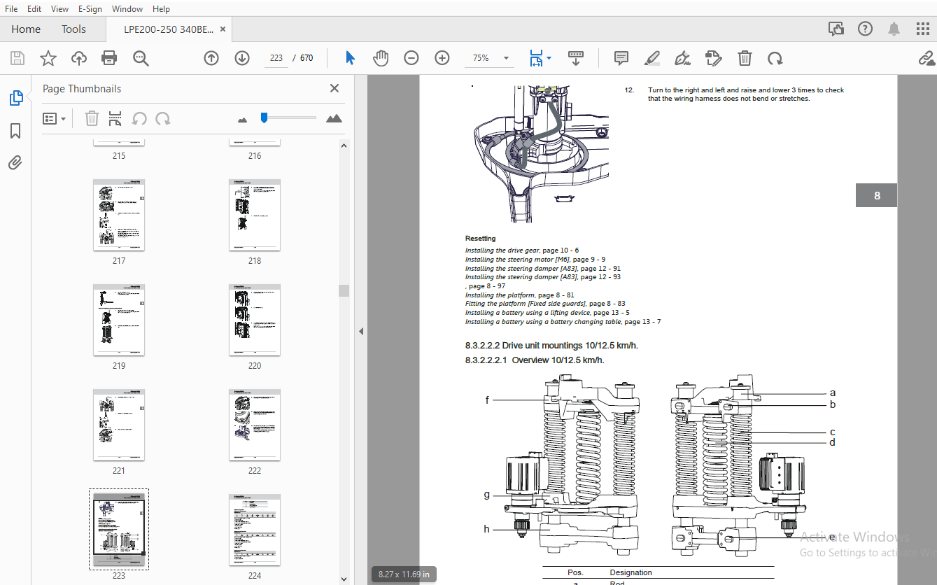
TABLE OF CONTENTS:
BT Forklift Toyota LPE200 LPE220 LPE250 LPE340BE Repair Manual – PDF DOWNLOAD
1 General introduction..................................................................................  9
	1.1 Images and other information....................................................................  9
	1.2 Warning levels and symbols......................................................................  9
	1.3 Pictograms......................................................................................  9
	1.4 Abbreviations................................................................................... 10
2 General safety rules.................................................................................. 15
	2.1 Authorised personnel............................................................................ 15
	2.2 Product modification............................................................................ 15
		2.2.1 Responsible............................................................................... 15
		2.2.2 What is it permitted to modify?........................................................... 15
	2.3 Work safety..................................................................................... 16
	2.4 Electrical system............................................................................... 17
		2.4.1 Electrostatic risks....................................................................... 17
		2.4.2 Battery handling.......................................................................... 18
	2.5 Safe lifting.................................................................................... 18
	2.6 Software........................................................................................ 19
	2.7 Hydraulic system................................................................................ 19
3 Operating principle................................................................................... 23
	3.1 Description..................................................................................... 23
		3.1.1 Battery is connected...................................................................... 23
		3.1.2 Login via keypad.......................................................................... 23
		3.1.3 Login via “ID key” option................................................................. 23
		3.1.4 Tiller arm lowered for driving............................................................ 23
		3.1.5 Driving in fork direction................................................................. 24
		3.1.6 Driving in the drive wheel direction...................................................... 24
		3.1.7 Braking in neutral........................................................................ 24
		3.1.8 Reverse braking........................................................................... 25
		3.1.9 Mechanical braking........................................................................ 25
		3.1.10 Emergency reversal....................................................................... 25
		3.1.11 Fork lifting............................................................................. 26
		3.1.12 Fork lowering............................................................................ 26
4 Parameters............................................................................................ 29
	4.1 Software........................................................................................ 29
	4.2 Display/change parameters....................................................................... 29
	4.3 Parameters on commissioning..................................................................... 29
		4.3.1 Setting parameters........................................................................ 29
		4.3.2 Setting collision sensor parameters (option).............................................. 29
		4.3.3 Setting battery parameters................................................................ 30
	4.4 Parameter list.................................................................................. 30
5 Installation.......................................................................................... 79
	5.1 Transport....................................................................................... 79
		5.1.1 Transporting the truck.................................................................... 79
		5.1.2 Transporting the fork carriage............................................................ 79
	5.2 Lifting the truck............................................................................... 80
		5.2.1 Lifting the truck......................................................................... 80
		5.2.2 Lift using a jack......................................................................... 80
	5.3 Commissioning................................................................................... 81
		5.3.1 Battery................................................................................... 81
			5.3.1.1 Battery installation................................................................ 81
6 Maintenance........................................................................................... 85
	6.1 Introduction.................................................................................... 85
	6.2 Maintenance instructions........................................................................ 85
		6.2.1 Cleaning.................................................................................. 85
		6.2.2 High-pressure washers..................................................................... 85
		6.2.3 Degreasing agents......................................................................... 86
		6.2.4 Cleaning the exterior..................................................................... 86
		6.2.5 Cleaning the chain........................................................................ 86
		6.2.6 Cleaning the motor compartment............................................................ 86
		6.2.7 Electric components....................................................................... 86
		6.2.8 Optical sensors and reflectors............................................................ 86
		6.2.9 Hydraulic system.......................................................................... 87
		6.2.10 Signs, warnings and adhesive labels...................................................... 87
			6.2.10.1 Placement of signs................................................................. 87
	6.3 Lubricants specification........................................................................ 88
	6.4 Periodic maintenance............................................................................ 89
7 Troubleshooting.......................................................................................105
	7.1 Initial troubleshooting.........................................................................105
	7.2 Concluding troubleshooting......................................................................106
	7.3 Auxiliary functions.............................................................................107
		7.3.1 Towing a defective truck..................................................................107
			7.3.1.1 Towing and transporting a defective truck...........................................107
		7.3.2 Emergency driving mode....................................................................107
			7.3.2.1 Emergency driving mode..............................................................107
		7.3.3 Error code history........................................................................107
			7.3.3.1 Error code history..................................................................107
		7.3.4 Extended error log........................................................................108
			7.3.4.1 Extended error log..................................................................108
		7.3.5 Built-in test function for the tiller arm.................................................108
			7.3.5.1 General.............................................................................108
			7.3.5.2 Display test........................................................................109
			7.3.5.3 Speed control.......................................................................109
			7.3.5.4 Safety reversing....................................................................109
			7.3.5.5 Controls for lifting/lowering.......................................................110
			7.3.5.6 Sensilift...........................................................................110
			7.3.5.7 Keypad..............................................................................111
		7.3.6 Digital input/output status...............................................................111
			7.3.6.1 Test mode "9".......................................................................111
			7.3.6.2 Test mode “12” SEU expansion unit (option)..........................................112
		7.3.7 Service information.......................................................................113
			7.3.7.1 Service information.................................................................113
		7.3.8 Hydraulic pressure........................................................................114
			7.3.8.1 Erroneous hydraulic system pressure.................................................114
	7.4 Troubleshooting using error codes...............................................................114
		7.4.1 First actions when an error code is displayed.............................................114
		7.4.2 List of error codes.......................................................................115
8 Chassis C0000.........................................................................................183
	8.1 Overview........................................................................................183
	8.2 Frame, chassis C0300............................................................................183
		8.2.1 Inspection of the rear chassis............................................................183
		8.2.2 Inspection covers C0340...................................................................184
			8.2.2.1 Motor compartment covers............................................................184
				8.2.2.1.1 Overview......................................................................184
				8.2.2.1.2 Replacing a service cover.....................................................185
					8.2.2.1.2.1 Removing a service cover................................................185
					8.2.2.1.2.2 Installing a service cover..............................................185
				8.2.2.1.3 Replacing a side cover........................................................185
					8.2.2.1.3.1 Removing a side cover...................................................185
					8.2.2.1.3.2 Installing a side cover.................................................186
				8.2.2.1.4 Replacing an emblem cover.....................................................186
					8.2.2.1.4.1 Removing an emblem cover................................................186
					8.2.2.1.4.2 Installing an emblem cover..............................................187
				8.2.2.1.5 Replacing an upper cover......................................................187
					8.2.2.1.5.1 Removing an upper cover.................................................187
					8.2.2.1.5.2 Installing an upper cover...............................................188
				8.2.2.1.6 Replacing a cover.............................................................188
					8.2.2.1.6.1 Removing a cover........................................................188
					8.2.2.1.6.2 Installing a cover......................................................189
		8.2.3 Support arms, stabilizers C0350...........................................................189
			8.2.3.1 Replacing the roller on the torsion tube............................................189
				8.2.3.1.1 Removing the roller on the torsion tube.......................................189
				8.2.3.1.2 Fit the roller on the torsion tube............................................190
			8.2.3.2 Replacing the wheel fork bushing....................................................191
				8.2.3.2.1 Removing the bushing..........................................................191
				8.2.3.2.2 Installing the bushing........................................................192
		8.2.4 Fork structure (low-lifter) C0380.........................................................192
			8.2.4.1 Overview............................................................................192
			8.2.4.2 Replacing the fork carriage.........................................................193
				8.2.4.2.1 Removing the fork carriage....................................................193
				8.2.4.2.2 Installing the fork carriage..................................................196
			8.2.4.3 Checking the fork carriage..........................................................199
			8.2.4.4 Replacing the torsion tube-linkage-wheel fork.......................................200
				8.2.4.4.1 Removing the torsion tube-linkage-wheel fork..................................200
				8.2.4.4.2 Fitting the torsion tube-linkage-wheel fork...................................202
			8.2.4.5 Checking the torsion tube-linkage-wheel fork........................................204
			8.2.4.6 Push rod weld.......................................................................204
			8.2.4.7 Checking the wheel fork flexibility.................................................208
			8.2.4.8 Checking the linkage................................................................208
			8.2.4.9 Checking the fork carriage..........................................................208
			8.2.4.10 Lubricating the beams..............................................................209
			8.2.4.11 Checking the fork lift height limitation...........................................209
			8.2.4.12 Checking the fork carriage play....................................................209
		8.2.5 Battery compartment parts C0390...........................................................210
			8.2.5.1 Overview............................................................................210
			8.2.5.2 Overview............................................................................211
			8.2.5.3 Description.........................................................................211
				8.2.5.3.1 Battery lock, quick...........................................................211
				8.2.5.3.2 Battery lock, fixed...........................................................211
			8.2.5.4 Checking the battery lock...........................................................212
			8.2.5.5 Checking the battery lock...........................................................212
			8.2.5.6 Adjusting the battery lock..........................................................212
	8.3 Frame/chassis components C0400..................................................................212
		8.3.1 ESD protection (anti-static braid)........................................................212
			8.3.1.1 Replacing the ground strap..........................................................212
				8.3.1.1.1 Removing the ground strap.....................................................212
				8.3.1.1.2 Installing a ground strap.....................................................213
		8.3.2 Motor mount/brackets C0450................................................................214
			8.3.2.1 Checking the motor mounts...........................................................214
			8.3.2.2 Drive unit mountings................................................................215
				8.3.2.2.1 Drive unit mountings 6/8 km/h.................................................215
					8.3.2.2.1.1 Overview 6/8 km/h.......................................................215
					8.3.2.2.1.2 Description.............................................................215
						8.3.2.2.1.2.1 Technical data....................................................215
						8.3.2.2.1.2.2 Technical data....................................................216
					8.3.2.2.1.3 Replacing the drive unit mountings 6/8 km/h.............................216
						8.3.2.2.1.3.1 Removing the drive unit mountings 6/8 km/h........................216
						8.3.2.2.1.3.2 Installing the drive unit mountings 6/8 km/h......................219
				8.3.2.2.2 Drive unit mountings 10/12.5 km/h.............................................223
					8.3.2.2.2.1  Overview 10/12.5 km/h..................................................223
					8.3.2.2.2.2 Description.............................................................224
						8.3.2.2.2.2.1 Technical data....................................................224
						8.3.2.2.2.2.2 Technical data....................................................224
						8.3.2.2.2.2.3 Technical data....................................................224
						8.3.2.2.2.2.4 Technical data....................................................225
						8.3.2.2.2.2.5 Technical data....................................................225
						8.3.2.2.2.2.6 Technical data....................................................225
						8.3.2.2.2.2.7 Technical data....................................................226
					8.3.2.2.2.3 Replacing the drive unit mountings 10/12.5 km/h.........................226
						8.3.2.2.2.3.1 Removing the drive unit mountings 10/12.5 km/h....................226
						8.3.2.2.2.3.2 Installing the drive unit mountings 10/12.5 km/h..................229
			8.3.2.3 PowerTrak...........................................................................234
				8.3.2.3.1 Description...................................................................234
					8.3.2.3.1.1 Design..................................................................234
				8.3.2.3.2 Increasing the spring tension.................................................235
				8.3.2.3.3 Increasing the spring tension.................................................237
				8.3.2.3.4 Releasing the spring tension..................................................240
				8.3.2.3.5 Releasing the spring tension..................................................241
				8.3.2.3.6 Adjusting tool V08-18302......................................................243
				8.3.2.3.7 Replacing the initial pressure spring.........................................244
					8.3.2.3.7.1 Removing the initial pressure spring....................................244
					8.3.2.3.7.2 Fitting the initial pressure spring.....................................245
				8.3.2.3.8 Replacing the PowerTrak spring................................................246
					8.3.2.3.8.1 Removing the PowerTrak spring...........................................246
					8.3.2.3.8.2 Installing the PowerTrak spring.........................................247
	8.4 Operator compartment, cab C0500.................................................................248
		8.4.1 Platform including fixing points C0560....................................................248
			8.4.1.1 Overview............................................................................248
			8.4.1.2 Overview............................................................................249
			8.4.1.3 Overview............................................................................250
			8.4.1.4 Checking the function of the platform switches......................................251
			8.4.1.5 Adjusting the position sensor [B120]................................................251
			8.4.1.6 Checking the platform...............................................................252
			8.4.1.7 Gas strut...........................................................................252
				8.4.1.7.1 Checking the gas strut........................................................252
				8.4.1.7.2 Replacing a gas strut.........................................................252
					8.4.1.7.2.1 Removing a gas strut....................................................252
					8.4.1.7.2.2 Installing a gas strut..................................................254
			8.4.1.8 Platform suspension.................................................................255
				8.4.1.8.1 Adjusting platform suspension.................................................255
				8.4.1.8.2 Adjusting the platform suspension [Fixed side guards].........................255
				8.4.1.8.3 Replacing the platform suspension.............................................256
					8.4.1.8.3.1 Removing the platform suspension........................................256
					8.4.1.8.3.2 Fitting the platform suspension.........................................256
			8.4.1.9 Safety switch, platform [B119]......................................................257
				8.4.1.9.1 Adjusting the position sensor play [B119].....................................257
				8.4.1.9.2 Checking the position sensor [B119]...........................................258
			8.4.1.10 Safety switch, platform [B119]/[B120]..............................................259
				8.4.1.10.1 Measuring the detection distance [B120]......................................259
				8.4.1.10.2 Replacing sensor [B119]......................................................259
					8.4.1.10.2.1 Removing the platform position sensor [B119]...........................259
					8.4.1.10.2.2 Fitting the platform position sensor [B119]............................259
				8.4.1.10.3 Replacing sensor [B120]......................................................260
					8.4.1.10.3.1 Removing the platform position sensor [B120]...........................260
					8.4.1.10.3.2 Fitting the platform position sensor [B120]............................260
			8.4.1.11 Replacing the platform.............................................................260
				8.4.1.11.1 Removing the platform........................................................260
				8.4.1.11.2 Removing the platform [Fixed side guards]....................................263
				8.4.1.11.3 Installing the platform......................................................263
				8.4.1.11.4 Fitting the platform [Fixed side guards].....................................265
	8.5 Safety equipment C0800..........................................................................267
		8.5.1 Operator protection C0840.................................................................267
			8.5.1.1 Fixed side guard....................................................................267
				8.5.1.1.1 Overview [Fixed side guards]..................................................267
				8.5.1.1.2 Replacing the fixed side guard................................................268
					8.5.1.1.2.1 Removing the fixed side guard...........................................268
					8.5.1.1.2.2 Fitting fixed side guards...............................................269
				8.5.1.1.3 Checking the position sensor [B119] [Fixed side guards].......................271
			8.5.1.2 Gate................................................................................272
				8.5.1.2.1 ..............................................................................272
				8.5.1.2.2 Checking the gate bar.........................................................273
				8.5.1.2.3 Checking the function of the gate switches....................................273
				8.5.1.2.4 Replacing a gas strut.........................................................273
					8.5.1.2.4.1 Removing the gate damper................................................273
					8.5.1.2.4.2 Removing the gate damper................................................274
					8.5.1.2.4.3 Fitting the gate damper.................................................274
					8.5.1.2.4.4 Fitting the gate damper.................................................275
				8.5.1.2.5 Replacing the pad.............................................................275
					8.5.1.2.5.1 Removing the pad........................................................275
					8.5.1.2.5.2 ........................................................................276
					8.5.1.2.5.3 Fitting pads............................................................277
					8.5.1.2.5.4 ........................................................................278
				8.5.1.2.6 Replacing the gate............................................................278
					8.5.1.2.6.1 ........................................................................278
					8.5.1.2.6.2 ........................................................................279
				8.5.1.2.7 Replacing the gate bar........................................................281
					8.5.1.2.7.1 Removing the gate bar...................................................281
					8.5.1.2.7.2 ........................................................................281
					8.5.1.2.7.3 Installing the gate bar.................................................282
					8.5.1.2.7.4 ........................................................................282
			8.5.1.3 Back rest...........................................................................283
				8.5.1.3.1 Overview [Back protection]....................................................283
				8.5.1.3.2 Checking the position sensor [B119 back protection]...........................283
				8.5.1.3.3 Replacing the back guard......................................................284
					8.5.1.3.3.1 Removing the back guard.................................................284
					8.5.1.3.3.2 Installing the back guard...............................................285
		8.5.2 Signs, warnings, labels C0850.............................................................285
			8.5.2.1 Checking signs and labels...........................................................285
			8.5.2.2 Placement of signs..................................................................285
9 Motors C1000..........................................................................................289
	9.1 Lubrication / cooling system C1300..............................................................289
		9.1.1 Mechanical cooling fan C1380..............................................................289
			9.1.1.1 Checking the cooling system.........................................................289
	9.2 Electric motors C1700...........................................................................289
		9.2.1 Electric pump motor C1710.................................................................289
			9.2.1.1 Overview............................................................................289
			9.2.1.2 Description.........................................................................290
				9.2.1.2.1 Construction..................................................................290
			9.2.1.3 Replacing the carbon brushes........................................................290
				9.2.1.3.1 Removing the carbon brushes...................................................290
				9.2.1.3.2 Fitting carbon brushes........................................................291
			9.2.1.4 Replacing the pump motor............................................................292
				9.2.1.4.1 Removing the pump motor [M3]..................................................292
				9.2.1.4.2 Installing the pump motor [M3]................................................293
		9.2.2 Electric steering motor C1730.............................................................295
			9.2.2.1 Overview............................................................................295
			9.2.2.2 Description.........................................................................295
				9.2.2.2.1 Technical data................................................................295
			9.2.2.3 Cleaning the ring gear..............................................................295
			9.2.2.4 Checking the electrical connections.................................................296
			9.2.2.5 Checking the steering motor gears...................................................296
			9.2.2.6 Checking the steering motor.........................................................296
			9.2.2.7 Lubricating the ring gear...........................................................296
			9.2.2.8 Check the drive gear's attachment...................................................296
			9.2.2.9 Replacing the steering motor........................................................296
				9.2.2.9.1 Removing the steering motor [M6]..............................................296
				9.2.2.9.2 Installing the steering motor [M6]............................................297
			9.2.2.10 Replacing the control unit.........................................................298
				9.2.2.10.1 Removing the control unit....................................................298
				9.2.2.10.2 Installing the control unit..................................................299
		9.2.3 Electric fan motor/fan C1740..............................................................300
			9.2.3.1 Overview............................................................................300
			9.2.3.2 Replacing the motor control fan.....................................................300
				9.2.3.2.1 Removing a motor control fan..................................................300
				9.2.3.2.2 Installing a motor control fan................................................302
		9.2.4 Electric drive motor C1760................................................................303
			9.2.4.1 Overview 1.8, 2.5 kW................................................................303
			9.2.4.2 Overview............................................................................304
			9.2.4.3 Checking the electrical connections.................................................305
			9.2.4.4 Checking the drive motor............................................................305
			9.2.4.5 Listen for any abnormal noise in the drive motor bearings...........................305
			9.2.4.6 Check the drive motor fitting (1.8 and 2.5 kW)......................................306
			9.2.4.7 Check the drive motor fitting (2.8 kW)..............................................306
			9.2.4.8 Checking the rotational speed sensor................................................306
			9.2.4.9 Check the rotational speed sensor fitting...........................................307
			9.2.4.10 Replacing the drive motor..........................................................307
				9.2.4.10.1 Removing the drive motor [M1]................................................307
				9.2.4.10.2 Removing the drive motor [M1]................................................309
				9.2.4.10.3 Removing the drive motor [M1]................................................311
				9.2.4.10.4 Installing the drive motor [M1]..............................................313
				9.2.4.10.5 Installing the drive motor [M1]..............................................315
				9.2.4.10.6 Installing the drive motor [M1]..............................................317
			9.2.4.11 Replacing the temperature sensor...................................................319
				9.2.4.11.1 Installing the temperature sensor............................................319
			9.2.4.12 Replacing the rotational speed sensor..............................................320
				9.2.4.12.1 Removing a rotational speed sensor...........................................320
				9.2.4.12.2 Installing a rotational speed sensor.........................................322
			9.2.4.13 Replacing the toothed wheel........................................................323
				9.2.4.13.1 Removing a toothed wheel.....................................................323
				9.2.4.13.2 Installing a toothed wheel...................................................324
10 Transmission/Drive gear C2000........................................................................327
	10.1 Drive unit, final gear C2500...................................................................327
		10.1.1 Drive unit/gear C2550 ...................................................................327
			10.1.1.1 Overview...........................................................................327
			10.1.1.2 Overview...........................................................................328
			10.1.1.3 Description .......................................................................328
				10.1.1.3.1 Design.......................................................................328
				10.1.1.3.2 Technical data...............................................................328
				10.1.1.3.3 Technical data...............................................................329
			10.1.1.4 Check the drive gear's attachment .................................................329
			10.1.1.5 Checking for leaks in the drive gear...............................................329
			10.1.1.6 Checking for noise in the drive gear...............................................330
			10.1.1.7 Replacing the drive gear ..........................................................330
				10.1.1.7.1 Removing the drive gear......................................................330
				10.1.1.7.2 Installing the drive gear....................................................332
			10.1.1.8 Replacing the wheel hub seal ......................................................333
				10.1.1.8.1 Removing the wheel hub seal..................................................333
				10.1.1.8.2 Installing the wheel hub seal................................................334
			10.1.1.9 Drive gear oil change..............................................................335
				10.1.1.9.1 Empty the drive gear oil.....................................................336
				10.1.1.9.2 Empty the drive gear oil.....................................................337
				10.1.1.9.3 Filling oil in the drive gear................................................338
				10.1.1.9.4 Filling oil in the drive gear................................................339
			10.1.1.10 Replacing the drive gear steering bearing ........................................339
				10.1.1.10.1 Removing the drive gear steering bearing....................................339
				10.1.1.10.2 Removing the drive gear steering bearing....................................340
				10.1.1.10.3 Installing the drive gear steering bearing..................................341
				10.1.1.10.4 Installing the drive gear steering bearing..................................342
			10.1.1.11 Stud replacement..................................................................342
				10.1.1.11.1 Removing a stud.............................................................342
				10.1.1.11.2 Installing a stud...........................................................343
11 Brake/wheel/track system C3000.......................................................................347
	11.1 Travel brake system C3100......................................................................347
		11.1.1 Description..............................................................................347
			11.1.1.1 Brake types........................................................................347
				11.1.1.1.1 Travel brake.................................................................347
				11.1.1.1.2 Emergency brake..............................................................347
				11.1.1.1.3 Parking brake................................................................347
	11.2 Parking brake details C3300....................................................................348
		11.2.1 Electrical parking brake, magnet brake C3370.............................................348
			11.2.1.1 Overview...........................................................................348
			11.2.1.2 Description........................................................................349
				11.2.1.2.1 Technical data...............................................................349
				11.2.1.2.2 Technical data...............................................................349
			11.2.1.3 Cleaning the parking brake.........................................................349
			11.2.1.4 Adjusting the parking brake gap....................................................350
			11.2.1.5 Adjusting the parking brake gap....................................................351
			11.2.1.6 Adjusting the parking brake gap....................................................351
			11.2.1.7 Tighten the parking brake mounting bolts...........................................352
			11.2.1.8 Emergency release of the parking brake.............................................352
			11.2.1.9 Checking the parking brake.........................................................353
			11.2.1.10 Replacing the brake hub...........................................................353
				11.2.1.10.1 Disassembling the brake hub.................................................353
				11.2.1.10.2 Installing a brake hub......................................................354
			11.2.1.11 Replacing the friction disc.......................................................354
				11.2.1.11.1 Removing the friction disc..................................................354
				11.2.1.11.2 Fitting the friction disc...................................................355
				11.2.1.11.3 Fitting the friction disc...................................................356
			11.2.1.12 Replacing the parking brake.......................................................357
				11.2.1.12.1 Removing the parking brake..................................................357
				11.2.1.12.2 Fitting the parking brake...................................................359
	11.3 Wheels C3500...................................................................................361
		11.3.1 Drive wheel C3530........................................................................361
			11.3.1.1 Overview...........................................................................361
			11.3.1.2 Measuring the drive wheel tread....................................................361
			11.3.1.3 Measuring the drive wheel tread....................................................362
			11.3.1.4 Check the drive wheel mountings....................................................362
			11.3.1.5 Check the drive wheel mountings....................................................363
			11.3.1.6 Replacing the drive wheel..........................................................363
				11.3.1.6.1 Disassembling the drive wheel................................................363
				11.3.1.6.2 Installing a drive wheel.....................................................364
		11.3.2 Support arm wheels/castor wheels C3540...................................................365
			11.3.2.1 Overview...........................................................................365
			11.3.2.2 Cleaning castor wheels.............................................................366
			11.3.2.3 Measuring the castor wheel tread...................................................366
			11.3.2.4 Measuring the castor wheel tread...................................................366
			11.3.2.5 Measuring the castor wheel tread...................................................367
			11.3.2.6 Measuring the castor wheel tread...................................................367
			11.3.2.7 Checking the castor wheels.........................................................367
			11.3.2.8 Replacing the castor wheel.........................................................367
				11.3.2.8.1 Removing the castor..........................................................367
				11.3.2.8.2 Removing the castor..........................................................368
				11.3.2.8.3 Installing a castor wheel....................................................370
				11.3.2.8.4 Installing a castor wheel....................................................371
			11.3.2.9 Replacing the castor wheel assembly................................................371
				11.3.2.9.1 Removing the castor wheel assembly...........................................371
				11.3.2.9.2 Installing the castor wheel assembly.........................................372
		11.3.3 Fork wheels/support arm wheels C3550.....................................................373
			11.3.3.1 Overview...........................................................................373
			11.3.3.2 Description........................................................................374
				11.3.3.2.1 Wheel wear...................................................................374
			11.3.3.3 Cleaning the fork wheels...........................................................374
			11.3.3.4 Measuring the fork wheel tread.....................................................375
			11.3.3.5 Checking the fork wheel mounting...................................................375
			11.3.3.6 Checking the fork wheel bushings...................................................375
			11.3.3.7 Replacing a single wheel...........................................................376
				11.3.3.7.1 Removing single wheels.......................................................376
				11.3.3.7.2 Removing single wheels.......................................................377
				11.3.3.7.3 Single wheel installation....................................................378
				11.3.3.7.4 Single wheel installation....................................................379
			11.3.3.8 Replacing bogie wheels.............................................................380
				11.3.3.8.1 Removing bogie wheels........................................................380
				11.3.3.8.2 Fitting the bogie wheel......................................................381
			11.3.3.9 Replacing a bogie link.............................................................382
				11.3.3.9.1 Removing a bogie link........................................................382
				11.3.3.9.2 Installing a bogie link......................................................383
12 Steering system C4000................................................................................387
	12.1 Description....................................................................................387
		12.1.1 Power steering...........................................................................387
	12.2 Mechanical steering system C4100...............................................................387
		12.2.1 Steering arm/wheel/lever C4110...........................................................387
			12.2.1.1 Overview tiller arm................................................................387
			12.2.1.2 Operating panel....................................................................389
				12.2.1.2.1 Overview operating panel.....................................................389
				12.2.1.2.2 Controls.....................................................................390
					12.2.1.2.2.1 Checking the hydraulic functions.......................................390
					12.2.1.2.2.2 Checking the stomach button............................................390
					12.2.1.2.2.3 Replacing the signal button/switch.....................................390
						12.2.1.2.2.3.1 Removing the signal button/switch................................390
						12.2.1.2.2.3.2 Fitting the signal button/switch.................................391
					12.2.1.2.2.4 Replacing the lift/lower button........................................391
						12.2.1.2.2.4.1 Removing the lift/lower button...................................391
						12.2.1.2.2.4.2 Fitting the lift/lower button....................................392
					12.2.1.2.2.5 Replacing a switch button..............................................394
						12.2.1.2.2.5.1 Removing a switch button.........................................394
						12.2.1.2.2.5.2 Fitting a switch button..........................................394
					12.2.1.2.2.6 Changing the position of the controls - support arm lift/fork lift.....395
					12.2.1.2.2.7 Replacing the safety reversing switch..................................395
						12.2.1.2.2.7.1 Removing the safety reversing switch.............................395
						12.2.1.2.2.7.2 Fitting the safety reversing switch..............................396
					12.2.1.2.2.8 Replacing the keypad...................................................397
						12.2.1.2.2.8.1 Removing the keypad..............................................397
						12.2.1.2.2.8.2 Installing a keypad..............................................397
				12.2.1.2.3 Replacing the operating panel................................................398
					12.2.1.2.3.1 Removing the operating panel...........................................398
					12.2.1.2.3.2 Installing an operating panel..........................................398
					12.2.1.2.3.3 Checking the speed control.............................................399
				12.2.1.2.4 Replacing the operating panel "Built-in".....................................400
					12.2.1.2.4.1 Removing the operating panel "Built-in"................................400
					12.2.1.2.4.2 Installing the operating panel "Built-in"..............................401
				12.2.1.2.5 Replacing the logic card.....................................................402
					12.2.1.2.5.1 Removing the logic card................................................402
					12.2.1.2.5.2 Installing a logic card................................................403
					12.2.1.2.5.3 Logic card [A5]........................................................404
			12.2.1.3 Tiller arm handle..................................................................405
				12.2.1.3.1 Replacing the handle to the tiller arm.......................................405
					12.2.1.3.1.1 Removing the tiller arm handle.........................................405
					12.2.1.3.1.2 Fitting the handle to the tiller arm...................................405
				12.2.1.3.2 Replacing the tiller arm handle "Built-in"...................................406
					12.2.1.3.2.1 Removing the tiller arm handle "Built-in"..............................406
					12.2.1.3.2.2 Installing the tiller arm handle "Built-in"............................407
			12.2.1.4 Tiller arm.........................................................................407
				12.2.1.4.1 Replacing the tiller arm.....................................................407
					12.2.1.4.1.1 Removing the tiller arm................................................407
					12.2.1.4.1.2 Fitting tiller arm.....................................................409
				12.2.1.4.2 Replacing the tiller arm "Built-in"..........................................411
					12.2.1.4.2.1 Removing the tiller arm "Built-in".....................................411
					12.2.1.4.2.2 Installing the tiller arm "Built-in"...................................413
				12.2.1.4.3 Checking the brake microswitches.............................................414
				12.2.1.4.4 Checking the play and the return travel......................................415
				12.2.1.4.5 Replacing the tiller arm cover...............................................415
					12.2.1.4.5.1 Removing the tiller arm cover..........................................415
					12.2.1.4.5.2 Installing the tiller arm cover........................................416
				12.2.1.4.6 Replacing the tiller arm cover "Built-in"....................................416
					12.2.1.4.6.1 Removing the tiller arm cover "Built-in"...............................416
					12.2.1.4.6.2 Installing the tiller arm cover "Built-in".............................417
			12.2.1.5 Steering yoke......................................................................418
				12.2.1.5.1 Overview.....................................................................418
				12.2.1.5.2 Overview steering servo......................................................419
				12.2.1.5.3 Overview Ergo................................................................420
				12.2.1.5.4 Replacing the steering yoke..................................................421
					12.2.1.5.4.1 Removing the steering yoke.............................................421
					12.2.1.5.4.2 Installing a steering yoke.............................................422
				12.2.1.5.5 Changing the tiller arm spring...............................................422
					12.2.1.5.5.1 Removing the tiller arm spring.........................................422
					12.2.1.5.5.2 Installing the tiller arm spring.......................................423
				12.2.1.5.6 Replacing the safety switch..................................................423
					12.2.1.5.6.1 Removing the safety switch [B60].......................................423
					12.2.1.5.6.2 Installing the safety switch [B60].....................................425
				12.2.1.5.7 Replacing the safety switch "Built-in".......................................425
					12.2.1.5.7.1 Removing the safety switch "Built-in"..................................425
					12.2.1.5.7.2 Installing the safety switch "Built-in"................................426
			12.2.1.6 Steering adapter...................................................................428
				12.2.1.6.1 Overview steering servo......................................................428
				12.2.1.6.2 Overview Mechanical steering.................................................429
				12.2.1.6.3 Overview steering servo......................................................431
				12.2.1.6.4 Overview Mechanical steering.................................................432
				12.2.1.6.5 Replacing the steering adapter...............................................433
					12.2.1.6.5.1 Removing the steering adapter..........................................433
					12.2.1.6.5.2 Removing the steering adapter..........................................434
					12.2.1.6.5.3 Removing the steering adapter..........................................435
					12.2.1.6.5.4 Removing the steering adapter..........................................436
					12.2.1.6.5.5 Installing a steering adapter..........................................437
					12.2.1.6.5.6 Installing a steering adapter..........................................439
					12.2.1.6.5.7 Installing a steering adapter..........................................440
					12.2.1.6.5.8 Installing a steering adapter..........................................442
				12.2.1.6.6 Replacing the steering adapter cover.........................................443
					12.2.1.6.6.1 Removing the steering adapter cover....................................443
					12.2.1.6.6.2 Installing the steering adapter cover..................................444
				12.2.1.6.7 Replacing a gas strut - height adjuster......................................444
					12.2.1.6.7.1 Removing a gas strut - height adjuster.................................444
					12.2.1.6.7.2 Installing a gas strut - height adjuster...............................444
					12.2.1.6.7.3 Checking the height adjuster...........................................445
				12.2.1.6.8 Replacing the height adjustment lock.........................................445
					12.2.1.6.8.1 Removing the height adjustment lock....................................445
					12.2.1.6.8.2 Removing the height adjustment lock....................................445
					12.2.1.6.8.3 Installing the height adjustment lock..................................447
					12.2.1.6.8.4 Installing the height adjustment lock..................................447
					12.2.1.6.8.5 Checking the height adjustment lock....................................448
				12.2.1.6.9 Replacing the mechanical stop of the steering shaft..........................448
					12.2.1.6.9.1 Removing the mechanical stop of the steering shaft (power steering)....448
					12.2.1.6.9.2 Fitting the mechanical stop of the steering shaft (power steering).....450
			12.2.1.7 Tiller arm wiring harness..........................................................452
				12.2.1.7.1 Replacing the tiller arm wiring harness......................................452
					12.2.1.7.1.1 Removing the tiller arm wiring harness.................................452
					12.2.1.7.1.2 Fitting the tiller arm wiring harness..................................455
			12.2.1.8 Replacing the steering bearing.....................................................461
				12.2.1.8.1 Removing the steering bearing................................................461
				12.2.1.8.2 Removing the steering bearing................................................462
				12.2.1.8.3 Fitting the steering bearing.................................................464
				12.2.1.8.4 Fitting the steering bearing.................................................465
			12.2.1.9 Replacing the rubber seals.........................................................467
				12.2.1.9.1 Removing rubber seals........................................................467
				12.2.1.9.2 Installing rubber seals......................................................467
	12.3 Electric steering system C4300.................................................................469
		12.3.1 Overview.................................................................................469
		12.3.2 Overview.................................................................................470
		12.3.3 Steering angle sensor C4350..............................................................470
			12.3.3.1 Description........................................................................470
				12.3.3.1.1 Design.......................................................................470
			12.3.3.2 Replacing the steering angle sensor servo unit.....................................471
				12.3.3.2.1 Removing the steering angle sensor...........................................471
				12.3.3.2.2 Installing steering angle sensor.............................................472
			12.3.3.3 Checking the reference sensor......................................................473
			12.3.3.4 Replacing the steering angle sensor mech. .........................................474
				12.3.3.4.1 Removing the steering angle sensor mech......................................474
				12.3.3.4.2 Installing the steering angle sensor mech....................................475
			12.3.3.5 Replacing the steering damper......................................................476
				12.3.3.5.1 Removing the steering damper [A83]...........................................476
				12.3.3.5.2 Removing the steering damper [A83]...........................................477
				12.3.3.5.3 Installing the steering damper [A83].........................................477
				12.3.3.5.4 Installing the steering damper [A83].........................................479
13 Electrical system C5000..............................................................................485
	13.1 Description....................................................................................485
		13.1.1 General..................................................................................485
	13.2 Using the anti-static carpet...................................................................485
	13.3 Programming tools..............................................................................485
		13.3.1 TruckCom.................................................................................485
			13.3.1.1 Connect the CAN interface to the truck.............................................485
		13.3.2 Software.................................................................................486
			13.3.2.1 Software update....................................................................486
	13.4 General electric equipment C5100...............................................................486
		13.4.1 Battery C5110............................................................................486
			13.4.1.1 Cleaning the battery...............................................................486
			13.4.1.2 Checking the connections...........................................................487
			13.4.1.3 Checking the battery cables........................................................487
			13.4.1.4 Checking the battery...............................................................487
			13.4.1.5 Checking cell and terminal protectors..............................................488
			13.4.1.6 Checking the level of the electrolyte..............................................488
			13.4.1.7 Checking the electrolyte density...................................................488
			13.4.1.8 Battery replacement................................................................488
				13.4.1.8.1 Replacing a battery using a lifting device...................................488
					13.4.1.8.1.1 Removing a battery using a lifting device..............................488
					13.4.1.8.1.2 Installing a battery using a lifting device............................489
				13.4.1.8.2 Replacing a battery using a battery changing table...........................491
					13.4.1.8.2.1 Removing a battery using a battery changing table......................491
					13.4.1.8.2.2 Installing a battery using a battery changing table....................491
		13.4.2 Battery Li-ion C5110.....................................................................493
			13.4.2.1 Battery module.....................................................................493
				13.4.2.1.1 Disconnection/connection.....................................................493
					13.4.2.1.1.1 Resetting/restarting the battery.......................................493
		13.4.3 General alarm signals (audible/visual) C5160.............................................494
			13.4.3.1 Horn...............................................................................494
				13.4.3.1.1 Overview.....................................................................494
				13.4.3.1.2 Checking the horn function...................................................495
		13.4.4 Battery charger (built-in) C5170.........................................................495
			13.4.4.1 Checking the battery charger cables................................................495
			13.4.4.2 Checking the battery charger parameters............................................495
		13.4.5 Battery cut out switch, main contactor C5190.............................................495
			13.4.5.1 Main contactor.....................................................................495
				13.4.5.1.1 Replacing the main contactor.................................................495
					13.4.5.1.1.1 Removing the main contactor............................................495
					13.4.5.1.1.2 Removing the main contactor............................................498
					13.4.5.1.1.3 Fitting the main contactor.............................................499
					13.4.5.1.1.4 Fitting the main contactor.............................................502
	13.5 Instrument panel, display C5200................................................................502
		13.5.1 Menu.....................................................................................502
			13.5.1.1 Menus..............................................................................502
			13.5.1.2 Menu navigation....................................................................503
			13.5.1.3 Menu overview......................................................................504
			13.5.1.4 Menu list..........................................................................504
			13.5.1.5 Menu information...................................................................505
			13.5.1.6 Show hour meter values.............................................................505
			13.5.1.7 Show error codes...................................................................506
			13.5.1.8 Show part numbers for software/hardware............................................506
			13.5.1.9 Built-in test ICH..................................................................506
			13.5.1.10 Show collisions...................................................................506
			13.5.1.11 Show/change parameters............................................................507
			13.5.1.12 Emergency driving mode............................................................507
			13.5.1.13 Calibration.......................................................................507
			13.5.1.14 Show/change PIN code..............................................................507
			13.5.1.15 PIN codes.........................................................................507
				13.5.1.15.1 General.....................................................................507
				13.5.1.15.2 PIN code for resetting the truck............................................508
				13.5.1.15.3 Programming PIN codes.......................................................508
				13.5.1.15.4 PIN code at delivery........................................................509
				13.5.1.15.5 PIN code defaults...........................................................510
		13.5.2 Hour counter, tachograph C5290...........................................................511
			13.5.2.1 Checking error log and operating hours.............................................511
	13.6 Control system travel function C5300...........................................................511
		13.6.1 Direction selector/speed regulator.......................................................511
		13.6.2 Safety reversing.........................................................................511
		13.6.3 Battery indicator........................................................................511
		13.6.4 Hour meter...............................................................................511
		13.6.5 Lifting and lowering control.............................................................511
		13.6.6 Signal buttons...........................................................................511
		13.6.7 Option buttons...........................................................................512
		13.6.8 Display..................................................................................512
		13.6.9 Symbols on keypad and display............................................................512
		13.6.10 Weighing system.........................................................................512
		13.6.11 Pressure equalization...................................................................512
	13.7 Power system travel function C5400.............................................................513
		13.7.1 Transistor panel C5460...................................................................513
			13.7.1.1 Overview ACT.......................................................................513
			13.7.1.2 Overview ACC.......................................................................514
			13.7.1.3 Description........................................................................514
				13.7.1.3.1 General......................................................................514
			13.7.1.4 Checking the contactors............................................................515
			13.7.1.5 Checking the cable connections.....................................................515
			13.7.1.6 Checking the electric panel mounting...............................................515
			13.7.1.7 Cleaning the electric panel heatsink...............................................516
			13.7.1.8 Replacing the motor control panel..................................................516
				13.7.1.8.1 Removing the motor control panel.............................................516
				13.7.1.8.2 Installing the motor control panel...........................................517
				13.7.1.8.3 Installing the motor control panel...........................................518
	13.8 Control system, working function C5500.........................................................519
		13.8.1 Work function harnesses/fuse C5590.......................................................519
			13.8.1.1 Checking the wiring harnesses......................................................519
	13.9 Power system working function C5600............................................................519
		13.9.1 Pump contactor C5610.....................................................................519
			13.9.1.1 Replacing the pump contactor.......................................................519
				13.9.1.1.1 Removing the pump contactor..................................................519
				13.9.1.1.2 Fitting the pump contactor...................................................521
	13.10 Control/protection electronics C5700..........................................................523
		13.10.1 Protective electronics wiring harness and fuse C5790....................................523
			13.10.1.1 Check the CAN bus.................................................................523
			13.10.1.2 Check the CAN node................................................................523
	13.11 Protective sensors, position sensors C5800....................................................523
		13.11.1 Description.............................................................................523
			13.11.1.1 Pressure sensor...................................................................523
		13.11.2 Safety probes/sensors C5830.............................................................524
			13.11.2.1 Emergency switch off..............................................................524
				13.11.2.1.1 Description.................................................................524
					13.11.2.1.1.1 Task and function.....................................................524
				13.11.2.1.2 Checking the emergency switch function......................................524
			13.11.2.2 Gate switches [B121]/[B122].......................................................524
				13.11.2.2.1 Replacing the gate switch [B120]............................................524
					13.11.2.2.1.1 Removing the position sensor [B121]...................................524
					13.11.2.2.1.2 ......................................................................525
					13.11.2.2.1.3 Installing the position sensor [B121].................................526
					13.11.2.2.1.4 ......................................................................527
				13.11.2.2.2 Replacing the gate switch [B122]............................................527
					13.11.2.2.2.1 Removing the position sensor [B122]...................................527
					13.11.2.2.2.2 ......................................................................528
					13.11.2.2.2.3 Installing the position sensor [B122].................................529
					13.11.2.2.2.4 ......................................................................529
			13.11.2.3 Photocell.........................................................................530
				13.11.2.3.1 Overview [Photocells for fixed side guards].................................530
				13.11.2.3.2 Description.................................................................530
					13.11.2.3.2.1 Function..............................................................530
				13.11.2.3.3 Checking the photocell......................................................531
	13.12 Calibrations..................................................................................531
		13.12.1 Steering angle calibration..............................................................531
		13.12.2 Weight measuring calibration............................................................532
		13.12.3 Weight measuring calibration............................................................532
		13.12.4 Steering angle manual steering..........................................................533
		13.12.5 Weight measuring calibration............................................................533
14 Hydraulics/Pneumatics C6000..........................................................................537
	14.1 Overview.......................................................................................537
	14.2 Description....................................................................................537
		14.2.1 Hydraulic hygiene........................................................................537
			14.2.1.1 Definitions – hydraulic parts......................................................537
			14.2.1.2 Inside cleaning....................................................................538
			14.2.1.3 Packaging..........................................................................538
			14.2.1.4 Handling...........................................................................538
			14.2.1.5 Storage............................................................................538
			14.2.1.6 Work procedures....................................................................538
		14.2.2 Construction.............................................................................539
	14.3 Quick change connectors........................................................................539
		14.3.1 Overview quick change connectors.........................................................539
		14.3.2 Removing female quick change connectors..................................................539
		14.3.3 Installing female quick change connectors................................................540
		14.3.4 Removing a quick change connector (male).................................................541
		14.3.5 Installing a quick change connector (male)...............................................542
	14.4 Hydraulic unit C6100...........................................................................543
		14.4.1 Overview.................................................................................543
		14.4.2 Hydraulic oil tank C6110.................................................................544
			14.4.2.1 Overview...........................................................................544
			14.4.2.2 Cleaning the tank..................................................................544
			14.4.2.3 Checking the tank..................................................................544
			14.4.2.4 Oil change.........................................................................545
				14.4.2.4.1 Draining oil.................................................................545
				14.4.2.4.2 Topping up with oil..........................................................545
			14.4.2.5 Replacing the tank.................................................................546
				14.4.2.5.1 Removing the tank............................................................546
				14.4.2.5.2 Fitting the tank.............................................................547
		14.4.3 Filter, filter housing C6130.............................................................547
			14.4.3.1 Air filter.........................................................................547
				14.4.3.1.1 Cleaning the air filter......................................................547
			14.4.3.2 ...................................................................................548
				14.4.3.2.1 Replacing the suction filter.................................................548
					14.4.3.2.1.1 Removing suction filter................................................548
					14.4.3.2.1.2 Installing the suction filter..........................................548
			14.4.3.3 Oil filter replacement.............................................................548
				14.4.3.3.1 Oil filter replacement.......................................................548
			14.4.3.4 Replacing the return filter........................................................549
				14.4.3.4.1 Removing the return filter...................................................549
				14.4.3.4.2 Fitting the return filter....................................................550
		14.4.4 Hydraulic pump C6140.....................................................................551
			14.4.4.1 Overview...........................................................................551
			14.4.4.2 Description........................................................................551
				14.4.4.2.1 Construction.................................................................551
			14.4.4.3 Replacing the hydraulic pump.......................................................551
				14.4.4.3.1 Removing the hydraulic pump..................................................551
				14.4.4.3.2 Removing the hydraulic pump..................................................552
				14.4.4.3.3 Installing the hydraulic pump................................................553
				14.4.4.3.4 Installing the hydraulic pump................................................554
		14.4.5 .........................................................................................555
			14.4.5.1 Checking the pressure limiting valve...............................................555
			14.4.5.2 Replacing the flow control valve...................................................556
				14.4.5.2.1 Removing the flow control valve..............................................556
				14.4.5.2.2 Fitting the flow control valve...............................................557
			14.4.5.3 Replacing the pressure limiting valve..............................................557
				14.4.5.3.1 Removing the pressure limiting valve.........................................557
				14.4.5.3.2 Fitting the pressure limiting valve..........................................558
			14.4.5.4 Adjusting the lifting capacity.....................................................558
				14.4.5.4.1 Adjusting the lifting capacity, reducing.....................................558
				14.4.5.4.2 Adjusting the lifting capacity, increasing...................................559
		14.4.6 Replacing the hydraulic unit.............................................................559
			14.4.6.1 Removing the hydraulic unit........................................................559
			14.4.6.2 Installing the hydraulic unit......................................................560
		14.4.7 Replacing the valve coil.................................................................561
			14.4.7.1 Removing the valve coil............................................................561
			14.4.7.2 Removing the valve coil............................................................562
			14.4.7.3 Fitting a solenoid valve...........................................................563
			14.4.7.4 Fitting a solenoid valve...........................................................564
		14.4.8 Replacing the pressure sensor............................................................564
			14.4.8.1 Removing the pressure sensor [B4]..................................................564
			14.4.8.2 Fitting the pressure sensor [B4]...................................................565
	14.5 Hydraulic system, fitted to chassis C6200......................................................566
		14.5.1 Main valve lift/reach/tilt C6210.........................................................566
			14.5.1.1 Overview...........................................................................566
	14.6 Hydraulic system, fitted on the mast C6300.....................................................566
		14.6.1 Mast hydraulic conduits C6320............................................................566
			14.6.1.1 Checks for leaks from hydraulic conduits and connections, hydraulic unit...........566
	14.7 Hydraulic cylinder C6600.......................................................................567
		14.7.1 Main lift cylinders C6610................................................................567
			14.7.1.1 Description........................................................................567
				14.7.1.1.1 Construction.................................................................567
			14.7.1.2 Checking the attachment of the lift cylinders......................................567
			14.7.1.3 Checking for leaks in the lift cylinder............................................567
			14.7.1.4 Replacing the main lift cylinders..................................................567
				14.7.1.4.1 Removing the lift cylinder, right side.......................................567
				14.7.1.4.2 Removing the lift cylinder, left side........................................568
				14.7.1.4.3 Fitting the lift cylinder, right side........................................570
				14.7.1.4.4 Fitting the lift cylinder, left side.........................................571
		14.7.2 PowerTrak cylinder C6680.................................................................572
			14.7.2.1 Replacing the PowerTrak cylinder...................................................572
				14.7.2.1.1 Removing the PowerTrak cylinder..............................................572
				14.7.2.1.2 Installing the PowerTrak cylinder............................................573
15 Work function - lifting masts C7000..................................................................577
16 Auxiliary equipment, installation equipment C8000....................................................581
17 Optional equipment/Extra equipment C9000.............................................................585
	17.1 Overview.......................................................................................585
	17.2 Extra electrical equipment C9400...............................................................586
		17.2.1 Extra power socket.......................................................................586
			17.2.1.1 Overview...........................................................................586
			17.2.1.2 Description........................................................................586
				17.2.1.2.1 DC/DC converter..............................................................586
		17.2.2 Truck log equipment, code lock C9420.....................................................587
			17.2.2.1 Overview...........................................................................587
			17.2.2.2 I_Site.............................................................................587
				17.2.2.2.1 Description..................................................................587
					17.2.2.2.1.1 I_Site.................................................................587
			17.2.2.3 Impact Manager.....................................................................588
				17.2.2.3.1 Impact sensor................................................................588
				17.2.2.3.2 Description..................................................................588
					17.2.2.3.2.1 Impact sensor..........................................................588
				17.2.2.3.3 Checking the impact sensor parameters........................................588
				17.2.2.3.4 Checking DHU/I-site [K110]...................................................588
			17.2.2.4 PreOpCheck.........................................................................588
	17.3 Other extra equipment C9500....................................................................590
		17.3.1 Fire extinguisher........................................................................590
			17.3.1.1 Description........................................................................590
				17.3.1.1.1 Fire extinguisher............................................................590
			17.3.1.2 Inspection of fire extinguisher....................................................591
		17.3.2 Horizontal E-bar.........................................................................592
			17.3.2.1 Overview...........................................................................592
			17.3.2.2 E-bar..............................................................................592
			17.3.2.3 Description........................................................................593
				17.3.2.3.1 E-bar........................................................................593
			17.3.2.4 Checking the E-bar lock............................................................594
		17.3.3 Spider expansion unit....................................................................594
			17.3.3.1 Description........................................................................594
				17.3.3.1.1 Spider expansion unit........................................................594
18 Instructions for disposal............................................................................597
	18.1 General........................................................................................597
	18.2 Marking of plastics............................................................................597
		18.2.1 General marking of products and packaging................................................597
		18.2.2 Marking according to the manufacturer’s standards........................................597
			18.2.2.1 Abbreviations......................................................................597
			18.2.2.2 Marking examples...................................................................598
	18.3 Pressure vessels...............................................................................598
		18.3.1 Gas struts...............................................................................598
	18.4 Sorting categories.............................................................................599
19 Wiring diagram.......................................................................................603
	19.1 Colour code table..............................................................................603
	19.2 List of fuses..................................................................................603
	19.3 Diagram........................................................................................604
		19.3.1 Component list...........................................................................604
		19.3.2 Component placement......................................................................607
		19.3.3 Detailed diagrams........................................................................621
20 Hydraulics schematics................................................................................639
	20.1 List of symbols................................................................................639
	20.2 Component list.................................................................................641
	20.3 Component location.............................................................................642
		20.3.1 Picture 1................................................................................642
		20.3.2 Picture 2................................................................................643
		20.3.3 Picture 3................................................................................644
	20.4 Diagram........................................................................................645
21 Tools................................................................................................649
	21.1 Tools for electric connectors..................................................................649
		21.1.1 AMP connectors...........................................................................649
		21.1.2 MQS connectors...........................................................................649
		21.1.3 CPC connectors...........................................................................650
		21.1.4 AMP Seal connectors......................................................................651
		21.1.5 Super Seal connectors....................................................................651
		21.1.6 Molex connectors.........................................................................652
	21.2 Lubricating tool...............................................................................653
	21.3 Special tools..................................................................................654
22 Service data and grease specifications...............................................................661
	22.1 General tightening torques.....................................................................661
		22.1.1 Galvanised, non-oiled screws.............................................................661
		22.1.2 Untreated, oiled screws..................................................................661
	22.2 Lubricants specification.......................................................................662
23 Technical data.......................................................................................665
	23.1 Truck Dimensions...............................................................................665
	23.2 Truck data.....................................................................................665
24 Index................................................................................................667
More products