Starting from:
$44
BT Forklift Toyota VRE125, VRE150, VRE125SF Repair Manual – PDF DOWNLOAD
BT Forklift Toyota VRE125, VRE150, VRE125SF Repair Manual – PDF DOWNLOAD
FILE DETAILS:
BT Forklift Toyota VRE125, VRE150, VRE125SF Repair Manual – PDF DOWNLOAD
Language : English
Pages : 1354
Downloadable : Yes
File Type : PDF
IMAGES PREVIEW OF THE MANUAL:
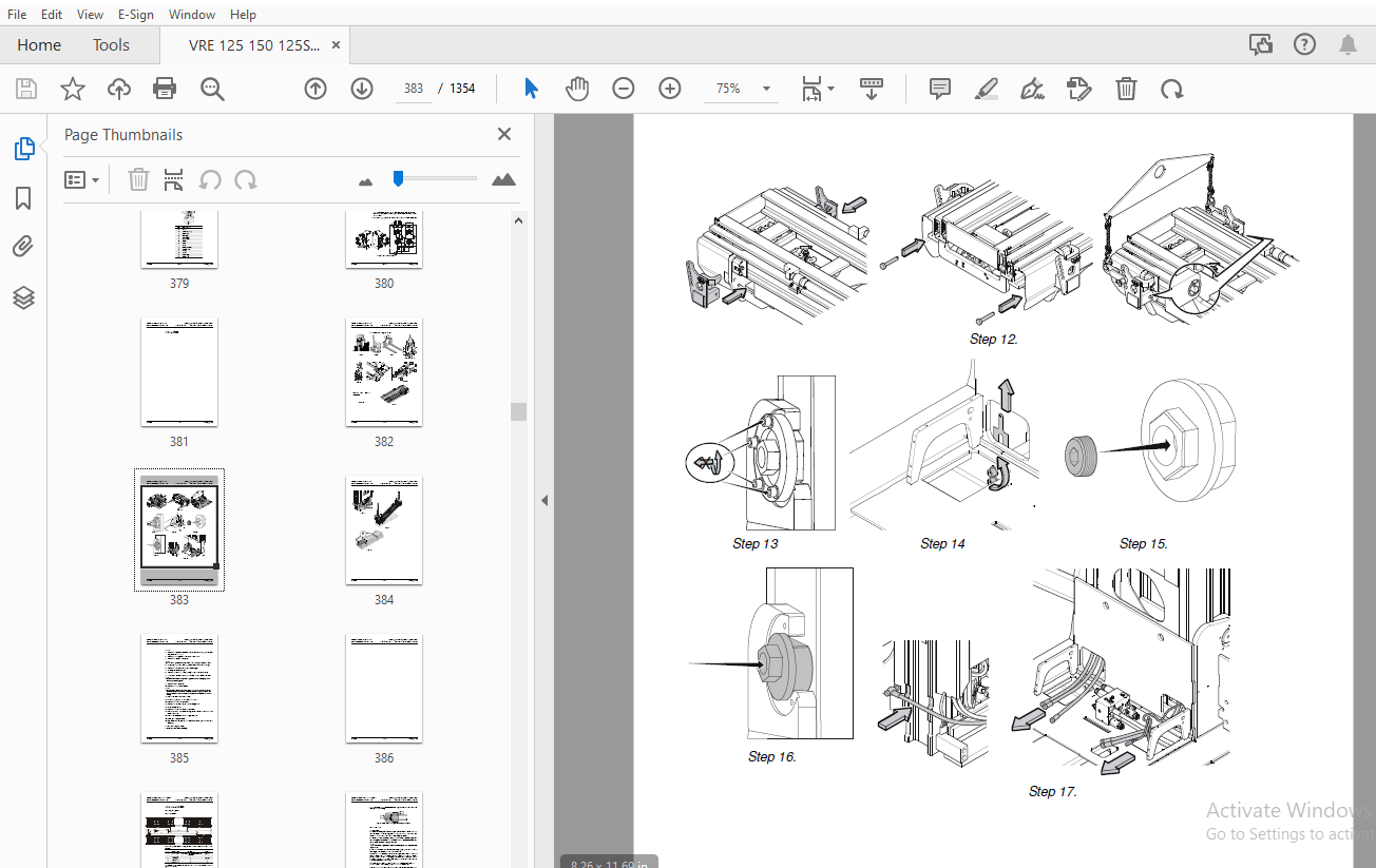
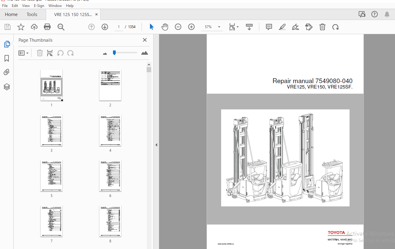
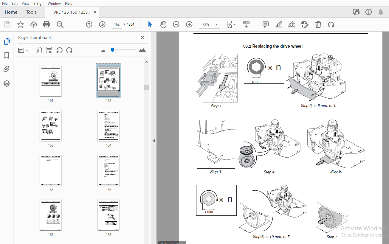
TABLE OF CONTENTS:
BT Forklift Toyota VRE125, VRE150, VRE125SF Repair Manual – PDF DOWNLOAD
1. Contents........................................................................................................................................................................0
2. General introduction............................................................................................................................................................0
	2.1 How to use this manual.....................................................................................................................................................0
	2.2 Warning levels and symbols.................................................................................................................................................0
	2.3 Pictograms.................................................................................................................................................................0
3. General safety rules............................................................................................................................................................0
	3.1 Work safety................................................................................................................................................................0
	3.2 Electrical system..........................................................................................................................................................0
	3.3 Safe lifting...............................................................................................................................................................0
	3.4 Truck modifications........................................................................................................................................................0
4. Chassis C0000...................................................................................................................................................................0
	4.1 Inspection covers C0340....................................................................................................................................................0
		4.1.1 Motor hood...........................................................................................................................................................0
		4.1.2 Battery inspection cover.............................................................................................................................................0
	4.2 Battery compartment parts C0390............................................................................................................................................0
		4.2.1 Battery locking mechanism............................................................................................................................................0
			Simple battery locking.................................................................................................................................................0
			Battery locking at battery changing equipment..........................................................................................................................0
		4.2.2 Battery side plate (option)..........................................................................................................................................0
	4.3 Operator's cab C0500.......................................................................................................................................................0
		4.3.1 Versions for cold-store cabs.........................................................................................................................................0
			Properties.............................................................................................................................................................0
			Emergency exit from the cab............................................................................................................................................0
	4.4 Cab windows C0530..........................................................................................................................................................0
		4.4.1 Electrically heated windows (Option).................................................................................................................................0
			Activation.............................................................................................................................................................0
	4.5 Cab door C0550.............................................................................................................................................................0
		Door handle on cab.........................................................................................................................................................0
	4.6 Operator's seat C0620......................................................................................................................................................0
		4.6.1 Seat switch [B49]....................................................................................................................................................0
	4.7 Cab heating/ventilation C0630..............................................................................................................................................0
	4.8 Driver controls (mechanical) C0640.........................................................................................................................................0
		4.8.1 Preconditions........................................................................................................................................................0
		4.8.2 Brake pedal..........................................................................................................................................................0
			Monitoring.............................................................................................................................................................0
			Indications in CID.....................................................................................................................................................0
		4.8.3 Accelerator..........................................................................................................................................................0
			Monitoring.............................................................................................................................................................0
			Indications in CID.....................................................................................................................................................0
	4.9 Mirrors C0740..............................................................................................................................................................0
		4.9.1 Mirror types.........................................................................................................................................................0
	4.10 Overhead guard/roof C0810.................................................................................................................................................0
		4.10.1 Protective overhead guard...........................................................................................................................................0
		4.10.2 Vertical E-bar......................................................................................................................................................0
	4.11 Finger/foot guards C0820..................................................................................................................................................0
	4.12 Operator protection C0840.................................................................................................................................................0
		4.12.1 Studs...............................................................................................................................................................0
		4.12.2 Protective grating..................................................................................................................................................0
	4.13 Signs, warnings, labels C0850.............................................................................................................................................0
5. Motors C1000....................................................................................................................................................................0
	5.0.1 Electric pump motor C1710 Description....................................................................................................................................0
	5.1............................................................................................................................................................................0
		5.1.1 Description..........................................................................................................................................................0
		5.1.2 Removing the pump motor..............................................................................................................................................0
		5.1.3 Fitting the pump motor...............................................................................................................................................0
		5.1.4 Replacing the temperature sensor.....................................................................................................................................0
		5.1.5 Replacing the speed sensor...........................................................................................................................................0
		5.1.6 Cleaning.............................................................................................................................................................0
		5.1.7 Replacing the oil pump...............................................................................................................................................0
		5.1.8 Replacing the bearing................................................................................................................................................0
		5.1.9 Electric steering motor C1730 (steering servo assembly) Description..................................................................................................0
		5.1.10 Description.........................................................................................................................................................0
		5.1.11 Layout of the flange holes..........................................................................................................................................0
		5.1.12 View from the underside of the steering motor: a: Attachment, b: Guide, c: Threaded hole for removing steering motor, M10×1,5.Replacing the steering servo motor....0
		5.1.13 Electric fan motor/fan C1740 Description............................................................................................................................0
		5.1.14 Description.........................................................................................................................................................0
		5.1.15 Indications in CID..................................................................................................................................................0
		5.1.16 Replacing the frequency converter fan...............................................................................................................................0
			Method.................................................................................................................................................................0
		5.1.17 Replacing the motor compartment fan.................................................................................................................................0
		5.1.18 Electric drive motor C1760 Replacing the frequency converter fan....................................................................................................0
			Method.................................................................................................................................................................0
		5.1.19 Replacing the motor compartment fan.................................................................................................................................0
	5.2............................................................................................................................................................................0
		5.2.1 Description..........................................................................................................................................................0
		5.2.2 Removing the drive motor.............................................................................................................................................0
		5.2.3 Fitting the drive motor..............................................................................................................................................0
		5.2.4 Replacing the temperature sensor.....................................................................................................................................0
		5.2.5 Replacing the speed sensor...........................................................................................................................................0
		5.2.6 Disassembly..........................................................................................................................................................0
		5.2.7 Cleaning.............................................................................................................................................................0
		5.2.8 Replacing the bearing................................................................................................................................................0
		5.2.9 Assembly.............................................................................................................................................................0
6. Drive gear C2000................................................................................................................................................................0
	6.1 Drive/Transmission Assembly................................................................................................................................................0
		6.1.1 Overview.............................................................................................................................................................0
	6.2 Description - Drive gear C2000.............................................................................................................................................0
		6.2.1 Oil change...........................................................................................................................................................0
		6.2.2 Leakage from the lower cover.........................................................................................................................................0
		6.2.3 Checking the oil level...............................................................................................................................................0
		6.2.4 Removing the drive gear..............................................................................................................................................0
		6.2.5 Steering bearing.....................................................................................................................................................0
			Replacing the steering bearing.........................................................................................................................................0
		6.2.6 Mounting the drive gear..............................................................................................................................................0
7. Brake system/Wheels C3000.......................................................................................................................................................0
	7.1 Brake system C3100.........................................................................................................................................................0
		7.1.1 Description..........................................................................................................................................................0
			Travel brake...........................................................................................................................................................0
			Parking brake..........................................................................................................................................................0
			Emergency brake........................................................................................................................................................0
		7.1.2 Drive motor brake C3180..............................................................................................................................................0
			Accelerator released...................................................................................................................................................0
			Changing the direction of travel.......................................................................................................................................0
	7.2 Support arm brake C3180....................................................................................................................................................0
		7.2.1 Overview.............................................................................................................................................................0
		7.2.2 Support arm brake (option) C3180.....................................................................................................................................0
		7.2.3 Test of support arm brake function...................................................................................................................................0
			Access.................................................................................................................................................................0
			Table for reading the maximum braking distance.........................................................................................................................0
		7.2.4 Support arm brake replacement........................................................................................................................................0
		7.2.5 Checking the brake unit's air gap....................................................................................................................................0
		7.2.6 Check of discs' thickness............................................................................................................................................0
		7.2.7 Assembling the brake unit............................................................................................................................................0
		7.2.8 Adjusting the air gap................................................................................................................................................0
	7.3 Parking brake C3370........................................................................................................................................................0
		7.3.1 Overview.............................................................................................................................................................0
		7.3.2 Description - Parking brake C3370....................................................................................................................................0
		7.3.3 Checking the parking brake's brake force.............................................................................................................................0
		7.3.4 Checking the parking brake air gap...................................................................................................................................0
		7.3.5 Replacing the brake unit.............................................................................................................................................0
		7.3.6 Disassembly and inspection of wear...................................................................................................................................0
	7.4 Emergency brake release....................................................................................................................................................0
		7.4.1 Releasing the brake in case of a faulty parking brake unit...........................................................................................................0
		7.4.2 Releasing the brake when the parking brake unit is intact............................................................................................................0
	7.5 Wheels C3500...............................................................................................................................................................0
	7.6 Drive wheel C3530..........................................................................................................................................................0
		7.6.1 Overview.............................................................................................................................................................0
		7.6.2 Replacing the drive wheel............................................................................................................................................0
		7.6.3 Wheel stud replacement...............................................................................................................................................0
		7.6.4 Support arm wheel C3550..............................................................................................................................................0
	7.7 Support arm wheel C3550....................................................................................................................................................0
		7.7.1 Overview.............................................................................................................................................................0
			VRE TH, unbraked wheel.................................................................................................................................................0
			VRE TH, braked wheel...................................................................................................................................................0
			VRE SF, unbraked wheel.................................................................................................................................................0
		7.7.2 Removing the support arm wheel, TH...................................................................................................................................0
		7.7.3 Mounting the support arm wheel, TH...................................................................................................................................0
		7.7.4 Removing the support arm wheel, TH...................................................................................................................................0
		7.7.5 Mounting the support arm wheel, TH...................................................................................................................................0
		7.7.6 Bearing replacement..................................................................................................................................................0
	7.8 Side guide wheel C3580 (option)............................................................................................................................................0
		7.8.1 Overview.............................................................................................................................................................0
		7.8.2 Description..........................................................................................................................................................0
		7.8.3 Replacing the side guide wheels (High profile).......................................................................................................................0
			Dismantling............................................................................................................................................................0
			Fitting................................................................................................................................................................0
		7.8.4 Adjusting the side guide wheels (High profile).......................................................................................................................0
		7.8.5 Replacing the side guide wheels (Low profile)........................................................................................................................0
			Dismantling............................................................................................................................................................0
			Assembly...............................................................................................................................................................0
		7.8.6 Adjusting the side guide wheels (Low profile)........................................................................................................................0
8. Steering system C4000...........................................................................................................................................................0
	8.1 Electric steering wheel C4310..............................................................................................................................................0
	8.2 Steering unit C4330........................................................................................................................................................0
	8.3 Steering angle reference sensor C4350......................................................................................................................................0
	8.4 Steering bearing C4380.....................................................................................................................................................0
	8.5 Wire guidance C4510........................................................................................................................................................0
		8.5.1 Description..........................................................................................................................................................0
			Wire signal/Antenna coils..............................................................................................................................................0
		8.5.2 Operating modes......................................................................................................................................................0
	8.6 Rail guidance C4510........................................................................................................................................................0
		8.6.1 Description..........................................................................................................................................................0
		8.6.2 Operating modes......................................................................................................................................................0
	8.7 Wire guidance, antenna C4540...............................................................................................................................................0
9. Electrical system C5000.........................................................................................................................................................0
	9.1 Battery C5110..............................................................................................................................................................0
		9.1.1 Battery recommendations..............................................................................................................................................0
		9.1.2 Measuring discharge current..........................................................................................................................................0
		9.1.3 Measuring voltage....................................................................................................................................................0
		9.1.4 Charging the battery.................................................................................................................................................0
		9.1.5 BDI algorithm and parameter setting..................................................................................................................................0
		9.1.6 Performance limitations due to battery status........................................................................................................................0
		9.1.7 Performance limitations due to battery status and parameter setting..................................................................................................0
		9.1.8 CID symbol...........................................................................................................................................................0
		9.1.9 Resetting the battery indicator (BDI)................................................................................................................................0
		9.1.10 Battery weight......................................................................................................................................................0
		9.1.11 Parameter overview, battery.........................................................................................................................................0
	9.2 General alarm signals (audible/visual) C5160...............................................................................................................................0
		9.2.1 Horn [P4]............................................................................................................................................................0
	9.3 Main contactor [Q10] C5190.................................................................................................................................................0
	9.4 Instrument panel C5200.....................................................................................................................................................0
		9.4.1 Operating controls...................................................................................................................................................0
			Adjustment.............................................................................................................................................................0
			Single-function control................................................................................................................................................0
			Central Information Display (CID)......................................................................................................................................0
			LED symbols............................................................................................................................................................0
			Screen.................................................................................................................................................................0
			Calibration functions..................................................................................................................................................0
		9.4.2 Load Information Display – LID.......................................................................................................................................0
			Technical data.........................................................................................................................................................0
			Connections............................................................................................................................................................0
			LED symbols............................................................................................................................................................0
			When the truck travels in the emergency travel mode, all symbols blink at the same time................................................................................0
			Symbols in the display part............................................................................................................................................0
	9.5 Weighing system............................................................................................................................................................0
	9.6 Overload limit.............................................................................................................................................................0
	9.7 Height measurement system..................................................................................................................................................0
		9.7.1 Monitoring...........................................................................................................................................................0
	9.8 Height preselector (Option)................................................................................................................................................0
		9.8.1 Symbols..............................................................................................................................................................0
		9.8.2 Travel warning.......................................................................................................................................................0
		9.8.3 Height preselector levels............................................................................................................................................0
		9.8.4 Level selection......................................................................................................................................................0
		9.8.5 Using the height preselector.........................................................................................................................................0
			Aisle and level selection..............................................................................................................................................0
			Presets................................................................................................................................................................0
		9.8.6 Program the level....................................................................................................................................................0
		9.8.7 Deleting a level.....................................................................................................................................................0
		9.8.8 Height preselector and TruckCom......................................................................................................................................0
		9.8.9 Lifting/lowering movement............................................................................................................................................0
			Parameter settings, lift/lowering movement.............................................................................................................................0
		9.8.10 Parameter overview, height preselector..............................................................................................................................0
	9.9 Transistor panel C5460.....................................................................................................................................................0
	9.10 Work function harnesses/fuse C5590........................................................................................................................................0
		9.10.1 Fuse panel – FCM [A9]...............................................................................................................................................0
			Fuse panel overview....................................................................................................................................................0
			Fuses..................................................................................................................................................................0
			[K20] Key relay........................................................................................................................................................0
			[S133] Emergency brake release.........................................................................................................................................0
	9.11 Main processor – MCU C5710................................................................................................................................................0
	9.12 Fork control unit – FCU C5720.............................................................................................................................................0
		9.12.1 Hydraulic functions.................................................................................................................................................0
			Turret head fork unit..................................................................................................................................................0
			Telescopic fork unit...................................................................................................................................................0
			Common and other functions.............................................................................................................................................0
	9.13 Expansion unit – GFU C5730................................................................................................................................................0
	9.14 Sending units and sensors C5800...........................................................................................................................................0
		9.14.1 Inductive sensors...................................................................................................................................................0
		9.14.2 Position sensor.....................................................................................................................................................0
			Steering reference sensor..............................................................................................................................................0
		9.14.3 Pressure sensor.....................................................................................................................................................0
		9.14.4 Pulse transducer....................................................................................................................................................0
			Steering sensor........................................................................................................................................................0
			Traversing sensor......................................................................................................................................................0
		9.14.5 Angle sensor........................................................................................................................................................0
	9.15 Safety probes/sensors C5830...............................................................................................................................................0
		9.15.1 Safety pedal [B31]..................................................................................................................................................0
			Indications in CID.....................................................................................................................................................0
		9.15.2 Safety switch, door [B31]...........................................................................................................................................0
			Location...............................................................................................................................................................0
			Task and function......................................................................................................................................................0
			Indications in CID.....................................................................................................................................................0
		9.15.3 Emergency switch off [S21]..........................................................................................................................................0
	9.16 Narrow aisle sensor C5840.................................................................................................................................................0
		9.16.1 Magnet sensor.......................................................................................................................................................0
		9.16.2 Photocell...........................................................................................................................................................0
		9.16.3 Narrow aisle detection..............................................................................................................................................0
			[B110] and [B111] – Magnet sensor......................................................................................................................................0
			Power supply...........................................................................................................................................................0
			Magnet detection.......................................................................................................................................................0
			[B111] and [B115] – Photocells.........................................................................................................................................0
		9.16.4 [B112]/[B113] End of aisle retardation..............................................................................................................................0
			Power supply...........................................................................................................................................................0
			Magnet detection.......................................................................................................................................................0
		9.16.5 [B116] and [B117] End of aisle stop.................................................................................................................................0
			Photocell..............................................................................................................................................................0
			Power supply...........................................................................................................................................................0
			Status – MCU inputs....................................................................................................................................................0
		9.16.6 [B172] – [B174] Aisle ID............................................................................................................................................0
			Photocell..............................................................................................................................................................0
			Power supply...........................................................................................................................................................0
			Status – GFU inputs....................................................................................................................................................0
10. Hydraulic system C6000.........................................................................................................................................................0
	10.1 Hydraulic unit C6100......................................................................................................................................................0
		10.1.1 Tank C6110..........................................................................................................................................................0
		10.1.2 Filter C6130........................................................................................................................................................0
		10.1.3 Hydraulic pump C6140................................................................................................................................................0
	10.2 Main valve unit C6210.....................................................................................................................................................0
		10.2.1 Definitions.........................................................................................................................................................0
		10.2.2 Valve unit design, DX...............................................................................................................................................0
			Inserts for quick change connector.....................................................................................................................................0
			Lift function..........................................................................................................................................................0
			Regenerative lowering function.........................................................................................................................................0
			Pressure limitation....................................................................................................................................................0
			Manual lowering function...............................................................................................................................................0
		10.2.3 Valve unit design, TX...............................................................................................................................................0
			Inserts for quick change connector.....................................................................................................................................0
			Lift function..........................................................................................................................................................0
			Regenerative lowering function (TX)....................................................................................................................................0
			The pump rotates clockwise and the rpm determines the speed of the function............................................................................................0
			Pressure limitation....................................................................................................................................................0
			Manual lowering function...............................................................................................................................................0
		10.2.4 Pressure sensor.....................................................................................................................................................0
	10.3 Mast valve units C6310....................................................................................................................................................0
		10.3.1 Valve unit design, SF...............................................................................................................................................0
			Inserts for quick change connector.....................................................................................................................................0
			Traversing.............................................................................................................................................................0
			Pressure limitation....................................................................................................................................................0
		10.3.2 Valve unit design, fork valve unit without extra functions..........................................................................................................0
			Inserts for quick change connector.....................................................................................................................................0
			Shunt function.........................................................................................................................................................0
		10.3.3 Valve unit design, fork valve unit with extra functions with load holding...........................................................................................0
			Inserts for quick change connector.....................................................................................................................................0
		10.3.4 Valve unit design, fork valve unit with extra functions without load holding........................................................................................0
	10.4 Calibration of proportional valves........................................................................................................................................0
	10.5 Hydraulic cylinders C6600.................................................................................................................................................0
		10.5.1 Main lift C6610.....................................................................................................................................................0
			Bleeding the main lift cylinders.......................................................................................................................................0
		10.5.2 Free lift C6620.....................................................................................................................................................0
		10.5.3 Tilt (Option) C6660.................................................................................................................................................0
		10.5.4 Other hydraulic cylinders C6670.....................................................................................................................................0
			Rotation...............................................................................................................................................................0
			Fork spread (Option)...................................................................................................................................................0
	10.6 Filtering the hydraulic oil...............................................................................................................................................0
	10.7 Pressure relief...........................................................................................................................................................0
11. Mast C7000.....................................................................................................................................................................0
	11.1 Disassembling the mast....................................................................................................................................................0
	11.2 Assembling the mast.......................................................................................................................................................0
12. Peripherals C8000..............................................................................................................................................................0
	12.1 Magnet layout.............................................................................................................................................................0
		12.1.1 Overview............................................................................................................................................................0
		12.1.2 Function............................................................................................................................................................0
			Rail guidance..........................................................................................................................................................0
			Wire guidance..........................................................................................................................................................0
		12.1.3 Alternative layout..................................................................................................................................................0
	12.2 Photocell layout..........................................................................................................................................................0
		12.2.1 “In narrow aisle”...................................................................................................................................................0
		12.2.2 Aisle ID............................................................................................................................................................0
		12.2.3 End of aisle stop...................................................................................................................................................0
13. Options/Extra equipment C9000..................................................................................................................................................0
	13.1 Extra electrical equipment C9300..........................................................................................................................................0
		13.1.1 Personal Protection System (PPS)....................................................................................................................................0
			General................................................................................................................................................................0
			Installation...........................................................................................................................................................0
			Service and spare parts................................................................................................................................................0
			Operator environment...................................................................................................................................................0
			Connections............................................................................................................................................................0
	13.2 Radio equipment C9330.....................................................................................................................................................0
	13.3 Extra lighting C9360......................................................................................................................................................0
	13.4 Extra warning lights/alarm C9370..........................................................................................................................................0
		13.4.1 Travel alarm 1 – Buzzer.............................................................................................................................................0
		13.4.2 Travel alarm 2 – Warning lamp.......................................................................................................................................0
		13.4.3 Direction indicators................................................................................................................................................0
	13.5 Positioning/TV equipment C9390............................................................................................................................................0
	13.6 Extra electrical equipment C9400..........................................................................................................................................0
		13.6.1 Extra power socket..................................................................................................................................................0
		13.6.2 Longitudinal positioning lamp.......................................................................................................................................0
	13.7 Truck log equipment, code lock C9420......................................................................................................................................0
		13.7.1 Toyota Wireless Information System (T.W.I.S.).......................................................................................................................0
	13.8 Other extra equipment C9500...............................................................................................................................................0
		13.8.1 Horizontal E-bar....................................................................................................................................................0
		13.8.2 Fire extinguisher...................................................................................................................................................0
14. Operation and connection sequences.............................................................................................................................................0
	14.1 Battery is connected......................................................................................................................................................0
		1. Battery is connected....................................................................................................................................................0
		2a. Login via unit connected to the MCU....................................................................................................................................0
		2b. Login via keypad.......................................................................................................................................................0
		2c. Login via “ID key” option..............................................................................................................................................0
		2d. Login to emergency driving mode........................................................................................................................................0
		3. Basic conditions........................................................................................................................................................0
		4. Driving in fork direction...............................................................................................................................................0
		5. Driving in the drive wheel direction....................................................................................................................................0
		6. Braking in neutral......................................................................................................................................................0
		7. Reverse braking.........................................................................................................................................................0
		8. Automatic braking.......................................................................................................................................................0
		9. Depressing the brake pedal..............................................................................................................................................0
		10. Manual control.........................................................................................................................................................0
		11. Wire search............................................................................................................................................................0
		13. In rail-guided narrow aisle............................................................................................................................................0
		14. Fork lifting...........................................................................................................................................................0
		15. Fork lowering..........................................................................................................................................................0
		16. Traversing to the right................................................................................................................................................0
		17.Traversing, left........................................................................................................................................................0
		18. Clockwise rotation.....................................................................................................................................................0
		19. Anticlockwise rotation.................................................................................................................................................0
		20. Auto-rotation, traversing to the left/clockwise rotation...............................................................................................................0
		21. Auto-rotation, traversing right/anticlockwise rotation.................................................................................................................0
		22. Traversing right (SF)..................................................................................................................................................0
		23. Traversing left (SF)...................................................................................................................................................0
		24. Extra hydraulic function <TBD>.........................................................................................................................................0
		25. Logout.................................................................................................................................................................0
		26. Emergency lowering.....................................................................................................................................................0
15. Parameters.....................................................................................................................................................................0
	15.1 General...................................................................................................................................................................0
	15.2 Parameter settings........................................................................................................................................................0
		15.2.1 Operator parameters.................................................................................................................................................0
			Access.................................................................................................................................................................0
			Parameter screens......................................................................................................................................................0
		15.2.2 Parameter menu (PAR)................................................................................................................................................0
			Access.................................................................................................................................................................0
			Parameter screens......................................................................................................................................................0
	15.3 Operator parameters.......................................................................................................................................................0
		15.3.1 Overview............................................................................................................................................................0
		15.3.2 Connection to logged-in operator....................................................................................................................................0
		15.3.3 Description.........................................................................................................................................................0
			Parameter 1 – Steering.................................................................................................................................................0
			Parameter 2, 3 6 and 7 – Maximum travel speed..........................................................................................................................0
			Parameters 4 and 5 – Acceleration/Deceleration.........................................................................................................................0
	15.4 General service parameters................................................................................................................................................0
		15.4.1 Overview............................................................................................................................................................0
		15.4.2 Description.........................................................................................................................................................0
			Parameter 101/104 – Service/Log-out....................................................................................................................................0
			Parameter 105/106/114/115/117/118/119 (Travel alarms 1 and 2)..........................................................................................................0
			Parameter 107/108/113 – Battery........................................................................................................................................0
			Parameter 109/110/111/112 – Collision sensor...........................................................................................................................0
			Parameter 116 (Door on cold store cabs)................................................................................................................................0
	15.5 Service parameters, travel functions......................................................................................................................................0
		15.5.1 Overview............................................................................................................................................................0
		15.5.2 Description.........................................................................................................................................................0
			Parameter 201 – Retardation when reversing.............................................................................................................................0
			Parameter 202/203/204 – Adjusting condition-related maximum travel speeds..............................................................................................0
			Parameters 205/206/207 – Adjusting function-related, maximum travel speeds.............................................................................................0
			Parameter 208 - Creep speed in travel direction control................................................................................................................0
			Parameter 209/210 – Adjustment of maximum travel speed above a certain lift height.....................................................................................0
			Parameters 211/212/213/214/215/216 – Adjusting application-related, maximum travel speeds..............................................................................0
	15.6 Service parameters, hydraulics............................................................................................................................................0
		15.6.1 Overview............................................................................................................................................................0
		15.6.2 Description.........................................................................................................................................................0
			Parameter 341/342 – Adjustment of application related, maximum lift/ lowering speeds...................................................................................0
			Parameter 343 – Oil filtration.........................................................................................................................................0
			Parameter 344 - Reduction of fork lowering speed before floor level....................................................................................................0
			Parameter 347/348 – Prevent the lifting/lowering of forks..............................................................................................................0
			Parameter 350 – Hydraulic function priority............................................................................................................................0
			Parameter 356 – Limitation of maximum travel speed under certain lift height with load on forks........................................................................0
			Parameters 361/362/363/364/365 /366 – Function related, maximum lifting/lowering speeds................................................................................0
			Parameter 367/368 – Lowering height limitation.........................................................................................................................0
			Parameter 369 – Fork height for limitation of lifting speed, forks not in home position................................................................................0
			Parameter 371 through 379 – Height preselector.........................................................................................................................0
			Parameter 380 through 386 – Lift height limitations in aisle...........................................................................................................0
			Parameters 387 through 394 – Configuration of lift height limitations..................................................................................................0
			Parameter 354/355 – Configuration of lift height limitations outside of aisle..........................................................................................0
			Parameters 395/396/397 – Function-related, maximum lift heights........................................................................................................0
			Parameters 398/399 – Operator profile dependent, maximum lift heights..................................................................................................0
	15.7 Service parameters, CID...................................................................................................................................................0
		15.7.1 Overview............................................................................................................................................................0
		15.7.2 Description.........................................................................................................................................................0
			Parameter 503 – Login method...........................................................................................................................................0
			Parameters 504/505/506/507 – Smart Access..............................................................................................................................0
			Parameter 508/509/512/513 – CID configuration..........................................................................................................................0
			Parameters 510/511 – Height pre-selection..............................................................................................................................0
	15.8 Service parameters, VNA...................................................................................................................................................0
		15.8.1 Overview............................................................................................................................................................0
		15.8.2 Description.........................................................................................................................................................0
			Parameters 601/602/603/604/605 – Truck over wire.......................................................................................................................0
			Parameter 606 – Wire guidance frequency................................................................................................................................0
			Parameters 607/608/609/610 – Speed reduction and stop at aisle ends....................................................................................................0
	15.9 Service parameters, FCU...................................................................................................................................................0
		15.9.1 Overview............................................................................................................................................................0
		15.9.2 Description.........................................................................................................................................................0
			Parameter 751 – Stroke length for half pallets.........................................................................................................................0
			Parameters 752/755/758 – Adjusting application dependent, maximum fork unit speeds.....................................................................................0
			Parameters 753/754/756/757 Acceleration/deceleration distance, fork unit functions.....................................................................................0
			Parameters 760/761/762/763 – Extra hydraulic functions.................................................................................................................0
			Parameter 764/765/766 – Reversed direction, fork unit functions........................................................................................................0
	15.10 General factory parameters...............................................................................................................................................0
		15.10.1 Overview...........................................................................................................................................................0
		15.10.2 Description........................................................................................................................................................0
			Parameters 1001/1003/1007/1008/1011/1070/1071/1072/1078/1080/1081/ 1082/1083 – General factory parameters with several choices.........................................0
			Parameter 1011 – Rated weight..........................................................................................................................................0
			Parameter 1072 – Boom length...........................................................................................................................................0
			Parameter 1078 – Camera switch.........................................................................................................................................0
			Parameter 1080 – Operating controls....................................................................................................................................0
			Parameter 1081 – Fork unit weight......................................................................................................................................0
			Parameter 1083 – Fork valve unit type..................................................................................................................................0
	15.11 Factory parameters, narrow aisle.........................................................................................................................................0
		15.11.1 Overview...........................................................................................................................................................0
		15.11.2 Description........................................................................................................................................................0
			Parameter 1020 – Distance between wire guidance antennas...............................................................................................................0
			Parameter 1021 – Aisle indication, wire guidance.......................................................................................................................0
			Parameter 1022 – Aisle indication, rail guidance.......................................................................................................................0
			Parameter 1023 – support for RFID (TNS)................................................................................................................................0
			Parameter 1024 – Aisle layout..........................................................................................................................................0
			Parameter 1025 – Sensor direction......................................................................................................................................0
	15.12 Factory parameters, activation of options................................................................................................................................0
		15.12.1 Overview...........................................................................................................................................................0
		15.12.2 Description........................................................................................................................................................0
	15.13 Factory parameters, calibration..........................................................................................................................................0
		Hydraulic system...........................................................................................................................................................0
16. Installation...................................................................................................................................................................0
	16.1 Transporting the truck....................................................................................................................................................0
	16.2 Transporting the mast.....................................................................................................................................................0
	16.3 Safe lifting..............................................................................................................................................................0
	16.4 Commissioning.............................................................................................................................................................0
		16.4.1 Common steps for both rail and wire guidance........................................................................................................................0
			Method.................................................................................................................................................................0
		16.4.2 Rail guidance.......................................................................................................................................................0
		16.4.3 Wire guidance.......................................................................................................................................................0
		16.4.4 Parameter setting...................................................................................................................................................0
			Setting battery parameters.............................................................................................................................................0
			Setting maximum travel speed...........................................................................................................................................0
			General................................................................................................................................................................0
		16.4.5 Configuration.......................................................................................................................................................0
			Calendar...............................................................................................................................................................0
			PIN-code handling......................................................................................................................................................0
		16.4.6 Test driving and checks.............................................................................................................................................0
			Functions..............................................................................................................................................................0
			In narrow aisle........................................................................................................................................................0
18. Maintenance....................................................................................................................................................................0
	18.1 Introduction..............................................................................................................................................................0
	18.2 Safety precautions for maintenance work...................................................................................................................................0
	18.3 Maintenance instructions..................................................................................................................................................0
		18.3.1 Cleaning and washing................................................................................................................................................0
		18.3.2 High-pressure washers...............................................................................................................................................0
		18.3.3 Degreasing agents...................................................................................................................................................0
		18.3.4 Cleaning the exterior...............................................................................................................................................0
		18.3.5 Cleaning the chain..................................................................................................................................................0
		18.3.6 Cleaning the motor compartment......................................................................................................................................0
		18.3.7 Electric components.................................................................................................................................................0
	18.4 Lubricants specification..................................................................................................................................................0
	18.5 Symbols...................................................................................................................................................................0
	18.6 Safety checks.............................................................................................................................................................0
	18.7 Periodic maintenance......................................................................................................................................................0
		18.7.1 Every 500 operating hours/180 days..................................................................................................................................0
		18.7.2 Every 1000 operating hours/360 days.................................................................................................................................0
		18.7.3 Every 2000 operating hours/720 days.................................................................................................................................0
		18.7.4 Every 3000 operating hours/1080 days................................................................................................................................0
18. Troubleshooting................................................................................................................................................................0
	18.1 Auxiliary functions.......................................................................................................................................................0
		18.1.1 Error log menu......................................................................................................................................................0
			Description............................................................................................................................................................0
			Access.................................................................................................................................................................0
		18.1.2 Error information menu..............................................................................................................................................0
			Description............................................................................................................................................................0
			Access.................................................................................................................................................................0
		18.1.3 Diagnostic screens..................................................................................................................................................0
			Description............................................................................................................................................................0
			Access.................................................................................................................................................................0
			Screen 1 – CID analogue inputs.........................................................................................................................................0
			Screen 2 – CID digital inputs..........................................................................................................................................0
			Screen 3 – MCU analogue inputs.........................................................................................................................................0
			Screen 4 – MCU digital inputs..........................................................................................................................................0
			Screen 5 – MCU digital outputs.........................................................................................................................................0
			Screen 6 – Pulse-width modulated outputs...............................................................................................................................0
			Screen 7 – FCU.........................................................................................................................................................0
			Screen 8 – FCU.........................................................................................................................................................0
			Screen 9 – GFU digital inputs/outputs..................................................................................................................................0
			Screen 11 – Temperatures...............................................................................................................................................0
			Screen 12 – Voltages...................................................................................................................................................0
			Screen 13 – travel function............................................................................................................................................0
			Screen 14 – Steering function..........................................................................................................................................0
			Screen 15 – Hydraulic functions 1......................................................................................................................................0
			Screen 17 – Hydraulic information......................................................................................................................................0
			Screen 18 – VNA functions..............................................................................................................................................0
			Screen 19 – Pressure sensor............................................................................................................................................0
	18.2 Initial troubleshooting...................................................................................................................................................0
	18.3 Troubleshooting using a blocking symbol...................................................................................................................................0
	18.4 Troubleshooting using error codes.........................................................................................................................................0
		18.4.1 CID – Group 1.......................................................................................................................................................0
		18.4.2 MCU – Group 2.......................................................................................................................................................0
		18.4.3 Drive system – Group 3..............................................................................................................................................0
		18.4.4 Hydraulic system – Group 4..........................................................................................................................................0
		18.4.5 Steering system – Group 5...........................................................................................................................................0
		18.4.6 Narrow aisle equipment – Group 6....................................................................................................................................0
		18.4.7 FCU – Group 7.......................................................................................................................................................0
		18.4.8 GFU – Group 8.......................................................................................................................................................0
	18.5 Troubleshooting without an error code.....................................................................................................................................0
19. Chassis C0000..................................................................................................................................................................0
	19.1 Hatches, covers C0340.....................................................................................................................................................0
		19.1.1 Open/close motor cover..............................................................................................................................................0
		19.1.2 Replacing the motor cover...........................................................................................................................................0
		19.1.3 Adjusting the motor cover...........................................................................................................................................0
		19.1.4 Remove/fit the floor................................................................................................................................................0
	19.2 Installing counterbalance C0370...........................................................................................................................................0
		Method.....................................................................................................................................................................0
	19.3 Cab windows C0530.........................................................................................................................................................0
		19.3.1 Fitting a window....................................................................................................................................................0
		19.3.2 Electrically heated windows (Option)................................................................................................................................0
			Activation of the function.............................................................................................................................................0
	19.4 Cab door C0550............................................................................................................................................................0
		19.4.1 Disassembly of the door lock........................................................................................................................................0
		19.4.2 Disassembly of the lock device......................................................................................................................................0
	19.5 Operator's seat C0620.....................................................................................................................................................0
		19.5.1 Adjustment:.........................................................................................................................................................0
			Seat heater button (Option)............................................................................................................................................0
		19.5.2 Replacing the seat assembly.........................................................................................................................................0
		19.5.3 Replacing the seat switch...........................................................................................................................................0
		19.5.4 Replacing the back rest.............................................................................................................................................0
		19.5.5 Replacing the chair seat............................................................................................................................................0
		19.5.6 Replacing the seat heater switch....................................................................................................................................0
		19.5.7 Installing the safety belt/armrest (Option).........................................................................................................................0
	19.6 Cab heating/ventilation C0630.............................................................................................................................................0
		19.6.1 Replacing the air filter on the cold store cab......................................................................................................................0
		19.6.2 Replacement of wiring harness with potentiometer....................................................................................................................0
		19.6.3 Replacing the air outlet............................................................................................................................................0
		19.6.4 Climate control knobs...............................................................................................................................................0
	19.7 Operator controls (mechanical) C0640......................................................................................................................................0
		19.7.1 Replacing pedals....................................................................................................................................................0
	19.8 Overhead guard/roof C0810.................................................................................................................................................0
		19.8.1 Overview............................................................................................................................................................0
		19.8.2 Removing the overhead guard.........................................................................................................................................0
		19.8.3 Fastening the overhead guard........................................................................................................................................0
		19.8.4 Removing the roof cassette..........................................................................................................................................0
		19.8.5 Fastening the roof cassette.........................................................................................................................................0
	19.9 Finger/foot guards C0820..................................................................................................................................................0
		19.9.1 Replacing a figure guard............................................................................................................................................0
	19.10 Operator protection C0840................................................................................................................................................0
		19.10.1 Replacing the fender...............................................................................................................................................0
		19.10.2 Adjusting tilt stops...............................................................................................................................................0
20. Motors C1000...................................................................................................................................................................0
	20.1 Electric pump motor C1710.................................................................................................................................................0
		20.1.1 Overview............................................................................................................................................................0
		20.1.2 Removing the pump motor.............................................................................................................................................0
		20.1.3 Fitting the pump motor..............................................................................................................................................0
		20.1.4 Replacing the temperature sensor....................................................................................................................................0
		20.1.5 Replacing the speed sensor..........................................................................................................................................0
		20.1.6 Cleaning............................................................................................................................................................0
		20.1.7 Replacing the RPM-sensor............................................................................................................................................0
		20.1.8 Replacing the bearing...............................................................................................................................................0
	20.2 Electric steering motor C1730.............................................................................................................................................0
		20.2.1 Overview............................................................................................................................................................0
		20.2.2 Replacing the steering servo motor..................................................................................................................................0
	20.3 Electric fan motor/fan C1740..............................................................................................................................................0
		20.3.1 Overview............................................................................................................................................................0
		20.3.2 Replacing the frequency converter fan...............................................................................................................................0
			Method.................................................................................................................................................................0
		20.3.3 Replacing the motor compartment fan.................................................................................................................................0
	20.4 Electric drive motor C1760................................................................................................................................................0
		20.4.1 Overview............................................................................................................................................................0
		20.4.2 Removing the drive motor............................................................................................................................................0
		20.4.3 Fitting the drive motor.............................................................................................................................................0
		20.4.4 Replacing the temperature sensor....................................................................................................................................0
		20.4.5 Replacing the speed sensor..........................................................................................................................................0
		20.4.6 Disassembly.........................................................................................................................................................0
		20.4.7 Cleaning............................................................................................................................................................0
		20.4.8 Replacing the bearing...............................................................................................................................................0
		20.4.9 Assembly............................................................................................................................................................0
21. Drive gear C2000...............................................................................................................................................................0
	21.1 Drive/Transmission Assembly...............................................................................................................................................0
		21.1.1 Overview............................................................................................................................................................0
		21.1.2 Oil change..........................................................................................................................................................0
		21.1.3 Leakage from the lower cover........................................................................................................................................0
		21.1.4 Checking the oil level..............................................................................................................................................0
		21.1.5 Removing the drive gear.............................................................................................................................................0
		21.1.6 Steering bearing....................................................................................................................................................0
			Replacing the steering bearing.........................................................................................................................................0
		21.1.7 Mounting the drive gear.............................................................................................................................................0
22. Brake system/Wheels C3000......................................................................................................................................................0
	22.1 Support arm brake C3180...................................................................................................................................................0
		22.1.1 Overview............................................................................................................................................................0
		22.1.2 Test of support arm brake function..................................................................................................................................0
			Access.................................................................................................................................................................0
			Table for reading the maximum braking distance.........................................................................................................................0
		22.1.3 Support arm brake replacement.......................................................................................................................................0
		22.1.4 Checking the brake unit's air gap...................................................................................................................................0
		22.1.5 Check of discs' thickness...........................................................................................................................................0
		22.1.6 Assembling the brake unit...........................................................................................................................................0
		22.1.7 Adjusting the air gap...............................................................................................................................................0
	22.2 Parking brake C3370.......................................................................................................................................................0
		22.2.1 Overview............................................................................................................................................................0
		22.2.2 Checking the parking brake's brake force............................................................................................................................0
		22.2.3 Checking the parking brake air gap..................................................................................................................................0
		22.2.4 Replacing the brake unit............................................................................................................................................0
		22.2.5 Disassembly and inspection of wear..................................................................................................................................0
	22.3 Emergency brake release...................................................................................................................................................0
		22.3.1 Releasing the brake in case of a faulty parking brake unit..........................................................................................................0
		22.3.2 Releasing the brake when the parking brake unit is intact...........................................................................................................0
	22.4 Wheels C3500..............................................................................................................................................................0
	22.5 Drive wheel C3530.........................................................................................................................................................0
		22.5.1 Overview............................................................................................................................................................0
		22.5.2 Replacing the drive wheel...........................................................................................................................................0
		22.5.3 Wheel stud replacement..............................................................................................................................................0
	22.6 Support arm wheel C3550...................................................................................................................................................0
		22.6.1 Overview............................................................................................................................................................0
			VRE TH, unbraked wheel.................................................................................................................................................0
			VRE TH, braked wheel...................................................................................................................................................0
			VRE SF, unbraked wheel.................................................................................................................................................0
		22.6.2 Removing the support arm wheel, TH..................................................................................................................................0
		22.6.3 Mounting the support arm wheel, TH..................................................................................................................................0
		22.6.4 Removing the support arm wheel, TH..................................................................................................................................0
		22.6.5 Mounting the support arm wheel, TH..................................................................................................................................0
		22.6.6 Bearing replacement.................................................................................................................................................0
	22.7 Side guide wheel C3580 (option)...........................................................................................................................................0
		22.7.1 Overview............................................................................................................................................................0
		22.7.2 Removing the side guide wheels......................................................................................................................................0
		22.7.3 Mounting the side guide wheels......................................................................................................................................0
		22.7.4 Replacing the bracket...............................................................................................................................................0
		22.7.5 Adjusting the side guide wheels.....................................................................................................................................0
23. Steering system C4000..........................................................................................................................................................0
	23.1 Electric steering wheel C4310.............................................................................................................................................0
		23.1.1 Replacing the steering wheel........................................................................................................................................0
		23.1.2 Replacing the steering knob.........................................................................................................................................0
		23.1.3 Adjustment..........................................................................................................................................................0
		23.1.4 Replacing pulse transducer [B13]....................................................................................................................................0
		23.1.5 Removing the steering console from the truck........................................................................................................................0
		23.1.6 Replacing the wiring harness in the steering console................................................................................................................0
		23.1.7 Fit the steering console in the truck...............................................................................................................................0
	23.2 Steering angle reference sensor C4350.....................................................................................................................................0
		23.2.1 Overview............................................................................................................................................................0
		23.2.2 Replacing the steering angle reference sensor [B59].................................................................................................................0
	23.3 Steering bearing C4380....................................................................................................................................................0
24. Electrical system C5000........................................................................................................................................................0
	24.1 Battery C5110.............................................................................................................................................................0
		24.1.1 Charging the battery................................................................................................................................................0
		24.1.2 Battery installation................................................................................................................................................0
	24.2 Main contactor C5190......................................................................................................................................................0
		24.2.1 Replacing the main contactor........................................................................................................................................0
		24.2.2 Overview............................................................................................................................................................0
		24.2.3 Replacing the main contactor........................................................................................................................................0
	24.3 Instrument panel C5200....................................................................................................................................................0
		24.3.1 Overview............................................................................................................................................................0
		24.3.2 Lever replacement/installation......................................................................................................................................0
			Required tools.........................................................................................................................................................0
			Method.................................................................................................................................................................0
		24.3.3 Replacing the multi-function control................................................................................................................................0
			Method.................................................................................................................................................................0
			Replacing the multi-function control's buttons.........................................................................................................................0
		24.3.4 Removing the control console from the truck.........................................................................................................................0
			Required tools.........................................................................................................................................................0
			Method.................................................................................................................................................................0
		24.3.5 Replacing the access card's circuit board...........................................................................................................................0
		24.3.6 Dismantling the control console.....................................................................................................................................0
			Required tools.........................................................................................................................................................0
			Method.................................................................................................................................................................0
		24.3.7 Installing an extra option button...................................................................................................................................0
		24.3.8 Replacing the travel direction selector with signal button..........................................................................................................0
		24.3.9 Replacing the display...............................................................................................................................................0
		24.3.10 Assembling the control console.....................................................................................................................................0
		24.3.11 Placing the control console in the truck...........................................................................................................................0
			Required tools.........................................................................................................................................................0
			Method.................................................................................................................................................................0
	24.4 Drive motor cables/resistors/fuses C5430..................................................................................................................................0
		24.4.1 Overview............................................................................................................................................................0
		24.4.2 Replacing copper braid, VRE125SF and VRE150.........................................................................................................................0
			Method.................................................................................................................................................................0
		24.4.3 Replacing copper braid, VRE125......................................................................................................................................0
			Method.................................................................................................................................................................0
		24.4.4 Replacing the fuse [F3], VRE125SF and VRE150........................................................................................................................0
		24.4.5 Replacing fuse [F3], VRE125.........................................................................................................................................0
		24.4.6 Replacing the fuse [F1], VRE125SF and VRE150........................................................................................................................0
		24.4.7 Replacing fuse [F1], VRE125.........................................................................................................................................0
		24.4.8 Replacing the terminal block B+, VRE125SF and VRE150................................................................................................................0
		24.4.9 Replacing terminal block B+, VRE125.................................................................................................................................0
		24.4.10 Replacing the terminal block B-, VRE125SF and VRE150...............................................................................................................0
		24.4.11 Replacing terminal block B-, VRE125................................................................................................................................0
		24.4.12 Replacing the motor cables.........................................................................................................................................0
	24.5 Transistor panel C5460....................................................................................................................................................0
		24.5.1 Overview............................................................................................................................................................0
		24.5.2 Removing ACT/ACH - VRE150 and VRE125SF..............................................................................................................................0
		24.5.3 Replacing ACT - VRE150 and VRE125SF.................................................................................................................................0
		24.5.4 Replacing ACH - VRE150 and VRE125SF.................................................................................................................................0
		24.5.5 Attaching ACT/ACH - VRE150 and VRE125SF.............................................................................................................................0
		24.5.6 Removing ACT/ACH - VRE125...........................................................................................................................................0
		24.5.7 Replacing ACT - VRE125..............................................................................................................................................0
		24.5.8 Replacing ACH - VRE125..............................................................................................................................................0
		24.5.9 Attaching ACT/ACH - VRE125..........................................................................................................................................0
	24.6 Work function harnesses/fuse C5590........................................................................................................................................0
		24.6.1 Fuse panel [A9].....................................................................................................................................................0
			Fuse panel overview....................................................................................................................................................0
			Replacing fuse.........................................................................................................................................................0
			Checking fuses.........................................................................................................................................................0
			Replacing the fuse panel...............................................................................................................................................0
	24.7 Main processor – MCU C5710................................................................................................................................................0
		24.7.1 Replacing the MCU...................................................................................................................................................0
	24.8 Fork control unit – FCU C5720.............................................................................................................................................0
		24.8.1 Replacing FCU [A7]..................................................................................................................................................0
		24.8.2 Replacing FCU [A7] SF...............................................................................................................................................0
	24.9 Safety probes/sensors C5830...............................................................................................................................................0
		24.9.1 Safety pedal........................................................................................................................................................0
			Replacing the safety pedal.............................................................................................................................................0
		24.9.2 Safety switch, door.................................................................................................................................................0
			Replacing the safety switch............................................................................................................................................0
		24.9.3 Emergency switch off................................................................................................................................................0
			Overview...............................................................................................................................................................0
			Removing the emergency switch off......................................................................................................................................0
	24.10 Calibrations.............................................................................................................................................................0
		24.10.1 Hydraulic levers...................................................................................................................................................0
		24.10.2 Reference sensor – height measurement/rotation angle...............................................................................................................0
			Calibrating height measurement.........................................................................................................................................0
			Calibrating rotational angle...........................................................................................................................................0
		24.10.3 Hydraulic valves...................................................................................................................................................0
			Free lift valve........................................................................................................................................................0
			Free lowering valve....................................................................................................................................................0
			Main lift valve........................................................................................................................................................0
			Main lowering valve....................................................................................................................................................0
			Valve for traversing right.............................................................................................................................................0
			Valve for traversing left..............................................................................................................................................0
			Valve for anticlockwise rotation.......................................................................................................................................0
		24.10.4 Mast transition between free lift and main lift....................................................................................................................0
		24.10.5 Pressure sensor....................................................................................................................................................0
			Zero point, free lift..................................................................................................................................................0
			Weight measurement, free lift..........................................................................................................................................0
			Zero point, main lift..................................................................................................................................................0
			Weight measurement, main lift..........................................................................................................................................0
		24.10.6 Wire guidance......................................................................................................................................................0
			Steering angle.........................................................................................................................................................0
			Frequency..............................................................................................................................................................0
			Offset.................................................................................................................................................................0
		24.10.7 Semi-automatic calibration of traversing...........................................................................................................................0
		24.10.8 Semi-automatic calibration of rotation.............................................................................................................................0
25. Hydraulic system C6000.........................................................................................................................................................0
	25.1 Hydraulic hygiene.........................................................................................................................................................0
		25.1.1 Washing.............................................................................................................................................................0
		25.1.2 Packaging...........................................................................................................................................................0
		25.1.3 Handling............................................................................................................................................................0
		25.1.4 Storage.............................................................................................................................................................0
		25.1.5 Work procedures.....................................................................................................................................................0
	25.2 Hydraulic system, bleeding................................................................................................................................................0
	25.3 Hose inspection...........................................................................................................................................................0
	25.4 Quick change connector....................................................................................................................................................0
		Overview...................................................................................................................................................................0
		Assembling the quick change connector......................................................................................................................................0
		Dismantling the quick change connector.....................................................................................................................................0
	25.5 Tank C6110................................................................................................................................................................0
		25.5.1 Emptying the tank...................................................................................................................................................0
		25.5.2 Filling the tank....................................................................................................................................................0
		25.5.3 Replacing the tank..................................................................................................................................................0
	25.6 Filter C6130..............................................................................................................................................................0
		25.6.1 Overview............................................................................................................................................................0
		25.6.2 Filter replacement (for air and oil)................................................................................................................................0
			Method.................................................................................................................................................................0
	25.7 Oil pump C6140............................................................................................................................................................0
	25.8 Mast valve units C6310....................................................................................................................................................0
		25.8.1 Replacing the control valve assembly [Q28]/[Q29]....................................................................................................................0
	25.9 Hydraulic cylinders C6600.................................................................................................................................................0
		25.9.1 Other hydraulic cylinders C6670.....................................................................................................................................0
			Rotation cylinder......................................................................................................................................................0
26. Mast C7000.....................................................................................................................................................................0
	26.1 Ordering a replacement mast...............................................................................................................................................0
	26.2 Disassembling the mast....................................................................................................................................................0
	26.3 Assembling the mast.......................................................................................................................................................0
	26.4 Adjusting/setting mast inclination on the truck...........................................................................................................................0
		Method.....................................................................................................................................................................0
	26.5 Main lifting chain system C7120...........................................................................................................................................0
		26.5.1 Check...............................................................................................................................................................0
		26.5.2 Lubrication.........................................................................................................................................................0
		26.5.3 Checking/adjusting lifting chains and guide flatness................................................................................................................0
		26.5.4 Checking/adjusting fork height – VRE150.............................................................................................................................0
	26.6 Forks C7410...............................................................................................................................................................0
		26.6.1 Overview............................................................................................................................................................0
		26.6.2 Inspection procedures...............................................................................................................................................0
			Inspection.............................................................................................................................................................0
			Inspection intervals...................................................................................................................................................0
			Surface cracks.........................................................................................................................................................0
			Difference in height between the fork tips.............................................................................................................................0
			Position lock..........................................................................................................................................................0
			Marking legibility.....................................................................................................................................................0
			Wear – fork blade and fork face........................................................................................................................................0
			Wear – fork mounting fixtures..........................................................................................................................................0
		26.6.3 Repairs and testing.................................................................................................................................................0
			Repairs................................................................................................................................................................0
			Testing the yield point................................................................................................................................................0
			Replacing forks........................................................................................................................................................0
	26.7 Turret head fork unit C7700...............................................................................................................................................0
		26.7.1 Setting backlash....................................................................................................................................................0
			Tools..................................................................................................................................................................0
	26.8 Traversing function, fork unit C7710......................................................................................................................................0
		26.8.1 Overview............................................................................................................................................................0
		26.8.2 Replacing sensor bearings [B9]......................................................................................................................................0
		26.8.3 Removing the hydraulic motor........................................................................................................................................0
			Method.................................................................................................................................................................0
		26.8.4 Mounting the hydraulic motor........................................................................................................................................0
			Method.................................................................................................................................................................0
		26.8.5 Replacing the drive unit shaft......................................................................................................................................0
			Method.................................................................................................................................................................0
		26.8.6 Replacing rollers on the unit arm...................................................................................................................................0
			Method.................................................................................................................................................................0
		26.8.7 Replacing the reference sensor [B7].................................................................................................................................0
	26.9 Swivel/rotation function, fork unit C7720.................................................................................................................................0
		26.9.1 Replacing rotation angle sensor [B8]................................................................................................................................0
	26.10 Shuttle fork unit C7800..................................................................................................................................................0
		26.10.1 Adjusting chains...................................................................................................................................................0
			Checking drive chain tension...........................................................................................................................................0
			Adjusting the drive chain..............................................................................................................................................0
		26.10.2 Replacing the idler roller.........................................................................................................................................0
		26.10.3 Replacing guide....................................................................................................................................................0
	26.11 Shuttle fork power unit C7820............................................................................................................................................0
		26.11.1 Replacing the reference sensor [B7] SF.............................................................................................................................0
		26.11.2 Replacing sensor bearings [B9] SF..................................................................................................................................0
27. Peripherals C8000..............................................................................................................................................................0
28. Options/Extra equipment C9000..................................................................................................................................................0
	28.1 E-bar C9500...............................................................................................................................................................0
		28.1.1 Overview............................................................................................................................................................0
		28.1.2 Fitting the E-bar...................................................................................................................................................0
		28.1.3 Installing accessories..............................................................................................................................................0
			Method.................................................................................................................................................................0
29. Instructions for disposal......................................................................................................................................................0
	29.1 General...................................................................................................................................................................0
	29.2 Marking of plastics.......................................................................................................................................................0
		29.2.1 General marking of products and packaging...........................................................................................................................0
		29.2.2 Marking according to the manufacturer’s standards...................................................................................................................0
			Abbreviations..........................................................................................................................................................0
			Marking examples.......................................................................................................................................................0
	29.3 Pressure vessels..........................................................................................................................................................0
		29.3.1 Gas struts..........................................................................................................................................................0
	29.4 Sorting categories........................................................................................................................................................0
30. Wiring diagram.................................................................................................................................................................0
	30.1 Components................................................................................................................................................................0
	30.2 Component location........................................................................................................................................................0
		Picture 1..................................................................................................................................................................0
		Picture 2..................................................................................................................................................................0
		Picture 3..................................................................................................................................................................0
		Picture 4..................................................................................................................................................................0
		Picture 5..................................................................................................................................................................0
		Picture 6..................................................................................................................................................................0
		Picture 7..................................................................................................................................................................0
		Picture 8..................................................................................................................................................................0
		Picture 9..................................................................................................................................................................0
		Picture 10.................................................................................................................................................................0
		Picture 11.................................................................................................................................................................0
		Picture 12.................................................................................................................................................................0
		Picture 13.................................................................................................................................................................0
		Picture 14.................................................................................................................................................................0
		Picture 15.................................................................................................................................................................0
		Picture 16.................................................................................................................................................................0
		Picture 17.................................................................................................................................................................0
		Picture 18.................................................................................................................................................................0
		Picture 19.................................................................................................................................................................0
		Picture 20.................................................................................................................................................................0
		Picture 21.................................................................................................................................................................0
		Picture 22.................................................................................................................................................................0
		Picture 23.................................................................................................................................................................0
		Picture 24.................................................................................................................................................................0
		Picture 25.................................................................................................................................................................0
		Picture 26.................................................................................................................................................................0
		Picture 27.................................................................................................................................................................0
		Picture 28.................................................................................................................................................................0
		Picture 29.................................................................................................................................................................0
		Picture 30.................................................................................................................................................................0
		Picture 31.................................................................................................................................................................0
		Picture 32.................................................................................................................................................................0
		Picture 33.................................................................................................................................................................0
		Picture 34.................................................................................................................................................................0
		Picture 35.................................................................................................................................................................0
		Picture 36.................................................................................................................................................................0
		Picture 37.................................................................................................................................................................0
		Picture 38.................................................................................................................................................................0
		Picture 40.................................................................................................................................................................0
		Picture 41.................................................................................................................................................................0
	30.3 Cable connections and terminal posts......................................................................................................................................0
		30.3.1 ACT [T1]............................................................................................................................................................0
		30.3.2 ACH [T2]............................................................................................................................................................0
		30.3.3 CID [A1]............................................................................................................................................................0
		30.3.4 MCU [A5]............................................................................................................................................................0
		30.3.5 FCU [A7]............................................................................................................................................................0
		30.3.6 GFU [A8]............................................................................................................................................................0
	30.4 Fuse panel [A9]...........................................................................................................................................................0
	30.5 Overview..................................................................................................................................................................0
	30.6 Detailed diagram From 6191182 - 6257600...................................................................................................................................0
	30.7 Detailed diagram From 6257601.............................................................................................................................................0
	30.8 CC Detailed diagram From 6191182 - 6257600................................................................................................................................0
	30.9 Detailed diagram From 6257601.............................................................................................................................................0
31. Hydraulics schematics..........................................................................................................................................................0
	31.1 Main valve unit, VRE duplex...............................................................................................................................................0
	31.2 Main valve unit, VRE triplex..............................................................................................................................................0
	31.3 Fork valve unit, turret head fork unit 2 functions........................................................................................................................0
	31.4 Fork valve unit, turret head fork unit 3 functions........................................................................................................................0
	31.5 Fork valve unit, SF.......................................................................................................................................................0
	31.6 Valve unit for tilt (Option)..............................................................................................................................................0
	31.7 List of symbols...........................................................................................................................................................0
	31.8 Detailed diagrams.........................................................................................................................................................0
		TH.........................................................................................................................................................................0
		SF.........................................................................................................................................................................0
32. Tools..........................................................................................................................................................................0
	32.1 AMP contacts..............................................................................................................................................................0
	32.2 MQS contacts..............................................................................................................................................................0
	32.3 CPC contacts..............................................................................................................................................................0
	32.4 Other tools...............................................................................................................................................................0
33. Service data and grease specifications.........................................................................................................................................0
	33.1 General tightening torques................................................................................................................................................0
		33.1.1 Galvanised, non-oiled screws........................................................................................................................................0
		33.1.2 Untreated, oiled screws.............................................................................................................................................0
	33.2 Oil and grease specification..............................................................................................................................................0
34. Technical data.................................................................................................................................................................0
	34.1 Basic data................................................................................................................................................................0
	34.2 Mast type and weight (kg).................................................................................................................................................0
	34.3 IP classes on components and units........................................................................................................................................0
	34.4 Battery sizes.............................................................................................................................................................0
	34.5 Truck dimensions..........................................................................................................................................................0
		34.5.1 VRE125, VRE150......................................................................................................................................................0
		34.5.2 VRE125SF............................................................................................................................................................0
1 file (117.3MB)

