$43
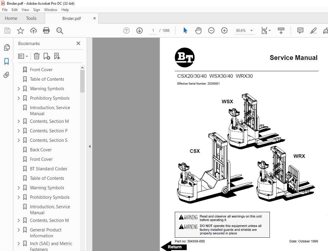
BT Prime-Mover Forklift CSX20/30/40 WSX30/40 WRX30 Service Manual – PDF DOWNLOAD
BT Prime-Mover Forklift CSX20/30/40 WSX30/40 WRX30 Service Manual – PDF DOWNLOAD
FILE DETAILS:
BT Prime-Mover Forklift CSX20/30/40 WSX30/40 WRX30 Service Manual – PDF DOWNLOAD
Language : English,
Pages :1066
Downloadable : Yes
File Type : PDF
TABLE OF CONTENTS:
BT Prime-Mover Forklift CSX20/30/40 WSX30/40 WRX30 Service Manual – PDF DOWNLOAD
Front Cover 1
Table of Contents 3
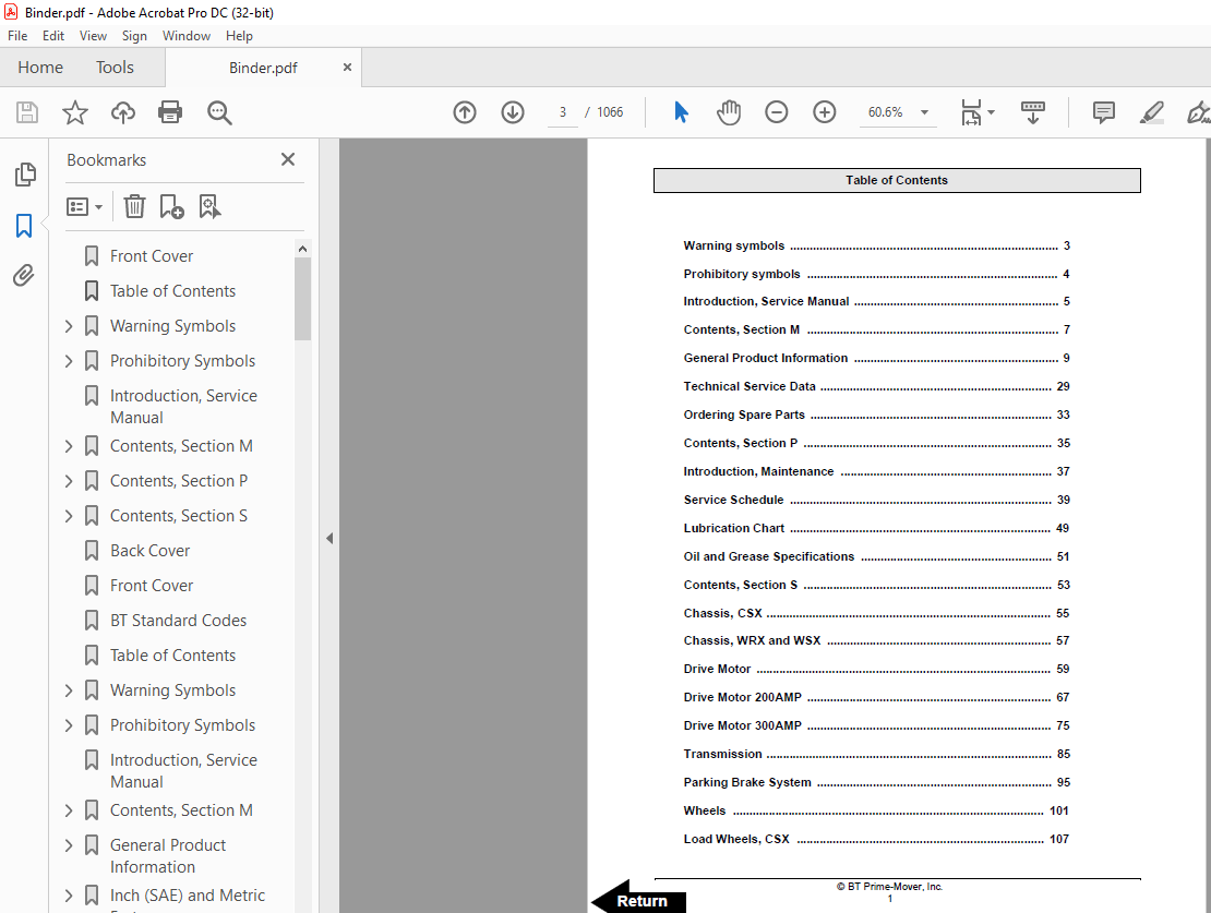
Warning Symbols 5
1 Warning Levels 5
Prohibitory Symbols 6
11 Ordinance Symbols 6
Introduction, Service Manual 7
Contents, Section M 9
General Product Information 11
1 Presentation of the Walkie Trucks CSX20/30/40, WSX30/40, and WRX30 11
11 Intended Application of the Trucks 11
12 Forbidden Application of the Truck 12
13 Truck Data 12
14 CSX Dimensions 13
15 WSX Dimensions 14
16 WRX Dimensions 15
17 Data Plate 16
2 Main Components 18
Inch (SAE) and Metric Fasteners 21
Introduction 22
Nomenclature, Threads 22
Strength Identification 23
Table #1 Bolts and Screws 24
Table #2 Studs and Nuts 25
Table #3 Torque Nuts 26
Table #4 Torque Nuts with Nylon Insert 27
Table #5 Conversion Table for Metric and English Units 28
Table #6 30
Technical Service Data 31
Ordering Spare Parts 35
Contents, Section P 37
Introduction, Maintenance 39
1 Safe Jacking Procedure 39
Service Schedule 41
1 Preventive Maintenance Schedule 41
2 Planned Maintenance Procedures 45
Services to be Performed Daily or at Each 8 Hour Operating Shift 45
Battery 45
Hydraulic System 45
Frame/Sheet Metal 45
Wheels/Tires 46
Functions/Operations 46
Services to be Performed Monthly or Every 250 Operating Hours 46
Inspection 46
Transmission 46
Brakes 46
Battery 47
Electrical Connections 47
Line Contactor Tips (NOT Sealed) 47
Motor Brushes 47
Drive Motor 48
Hydraulic Reservoir 48
Frame Lube 48
Pivot Points 48
Services to be Performed Annually or Every 1000 Operating Hours 48
Inspection 49
Transmission 49
Battery 49
Hydraulic System 50
Brakes 50
Lubrication Chart 51
Oil and Grease Specifications 53
1 Approved Oils and Grease 53
Contents, Section S 55
Chassis, CSX 57
1 General 57
2 Main Components 58
Chassis, WRX and WSX 59
1 General 59
2 Support Arms 60
Drive Motor 61
1 General Information 61
2 Operating Conditions 61
3 Troubleshooting 61
Drive Motor 200 AMP 69
1 Component Repair 70
2 Inspection and Troubleshooting 71
21 Drive End Head 71
22 Commutator End Head 71
23 Bearings 71
24 Brush and Commutator 72
25 Armature 72
26 Frame and Field Assembly 73
27 Assembly 75
3 When Changing Brushes 76
Drive Motor 300 AMP 77
4 Component Repair 78
5 Inspection and Troubleshooting 81
51 Drive End Head 81
52 Commutator End Head 81
53 Bearings 81
54 Brush and Commutator 82
55 Armature 82
56 Frame and Field Assembly 83
57 Assembly 85
6 When Changing Brushes 86
Transmission 87
1 System Description 87
2 Troubleshooting 88
3 Axle Seal Removal and Installation 89
31 Removal 89
32 Installation 89
4 Transmission Removal/Installation 90
41 Removal 90
42 Installation 91
5 Transmission Assembly 93
51 Disassembly 94
52 Assembly 94
Parking Brake System 97
1 Brake Theory of Operation 99
2 Brake Adjustment 100
3 Brake Shoe Removal/Installation 101
Wheels 103
1 Stabilizing Caster 103
11 Maintenance and Adjustments 104
12 Caster Adjustment 104
13 Troubleshooting 105
14 Stabilizing Caster 105
2 Drive Wheel 107
21 Removal 107
22 Installation 108
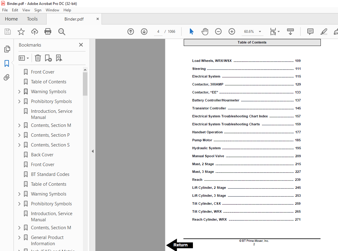
Load Wheels, CSX 109
Load Wheels, WRX/WSX 111
Steering 113
1 Control Handle Head 113
11 Removal 113
12 Installation 114
2 Control Handle Stem 114
21 Removal 114
22 Installation 114
Electrical System 117
1 Electrical Panel Components 117
2 List of Symbols 118
21 Circuit Diagram 1(5) 120
22 Circuit Diagram 2(5) 121
23 Circuit Diagram 3(5) 122
24 Circuit Diagram 4(5) 123
25 Circuit Diagram 5(5) 124
3 Description of Function 125
31 General 125
32 Adjustable Settings 125
33 References 125
34 Key Switch S17 in the ON Position 125
35 The Operating Arm in Drive Position, S10, Brake Switch Closed 126
36 Driving, Fork Direction 126
37 Driving, Steer Wheel Direction 126
38 Reversing/Motor Brake Fork Direction to Steer Wheel Direction 126
39 Reversing/Motor Brake Steer Wheel Direction to Fork Direction 126
310 Reverser Switch 127
311 Lifting the Forks 127
312 Lowering the Forks 127
313 Horn 127
4 Options 128
41 Lifting the Forks (Manual Valve) 128
42 Tilting the Forks 128
43 Sideshifting the Forks 128
44 Extend/Retract the Forks 128
Contactor, 300 AMP 131
1 Maintenance 131
11 Removal/Replacement of Contact Tips 132
Contactor, “EE” 135
2 Maintenance 136
21 Removal/Replacement of Contact Tips 136
Battery Controller/Hourmeter 139
1 General 139
2 Electrical 139
21 Voltage 139
3 Battery Controller (BC) 140
31 General 140
32 Reset 142
33 Key Switch 142
34 Hourmeter 142
4 Troubleshooting 143
41 Battery Discharge Indicator (BDI) 143
42 Hourmeter 145
Transistor Controller 147
1 Motor Circuit 147
2 Control Circuit 148
3 Technical Specification 150
4 Adjustment of Controller 152
41 Connection of Handset 152
5 Maintenance 153
51 Safety 153
52 Cleaning 153
6 Diagnostics and Troubleshooting 154
61 Handset Diagnostics 154
62 Troubleshooting 154
63 Troubleshooting Chart Using the Handset 157
Electrical System Troubleshooting Chart Index 159
Electrical System Troubleshooting Charts 161
Handset Operation 179
1 Operating Modes 180
2 Peace of Mind Programming 184
3 Handset Self Test 185
Pump Motor 187
1 Component Repair 188
2 Inspection and Troubleshooting 190
21 Drive End Head 190
22 Commutator End Head 190
23 Bearings 190
24 Brush and Commutator 191
25 Armature 191
26 Frame and Field Assembly 192
27 Assembly 194
3 When Changing Brushes 195
Hydraulic System 197
1 General 197
2 Description of Function 197
21 Hydraulic Schematic 197
CSX Hydraulic Schematic 198
WRX Hydraulic Schematic 199
WSX Hydraulic Schematic 200
22 Main Components 201
23 Description 201
3 Maintenance 202
31 Maintenance and Adjustments 202
32 Troubleshooting 203
Relief Valve 205
Figure 6110 206
Solenoid Operated Valve 207
Pump and Motor 207
Reservoir and Pump 208
Manual Spool Valve 211
Figure 0640 211
Figure 6160 212
Removal 213
Disassembly and Inspection 214
Assembly 215
Mast, 2 Stage 217
1 Shimming 219
11 Shimming the Carriage 219
12 Shimming the Rails 220
2 Two Stage Mast 222
21 Removal 222
22 Installation 224
23 Disassembly 225
24 Assembly 226
Mast, 3 Stage 229
1 Shimming 230
11 Shimming the Carriage 230
12 Shimming the Rails 231
2 Three Stage Mast 234
21 Removal 234
22 Installation 235
23 Disassembly 236
24 Assembly 237
Reach 241
1 Maintenance 241
2 Reach Repair 242
21 Disassembly 242
22 Assembly 243
Lift Cylinder, 2 Stage 247
1 Two Stage Full Freelift Mast Freelift Cylinder Repair 248
12 Disassembly 248
13 Assembly 248
14 Installation 249
2 Two Stage Full Freelift Mast Staging Cylinder Repair 250
21 Removal 250
22 Disassembly 250
23 Assembly 250
24 Installation 251
3 Two Stage Mast Lift Cylinder Repair 252
31 Removal 252
32 Disassembly 252
33 Assembly 252
34 Installation 253
Lift Cylinder, 3 Stage 255
1 Freelift Cylinder Repair 256
11 Removal 256
12 Disassembly 256
13 Assembly 256
14 Installation 257
2 Staging Cylinder Repair 258
21 Removal 258
22 Disassembly 258
23 Assembly 258
24 Installation 259
Tilt Cylinder, CSX 261
1 Removal 262
2 Disassembly 262
3 Inspection 263
4 Assembly 264
5 Installation 264
Tilt Cylinder, WRX 267
1 Removal 268
2 Disassembly 268
3 Inspection 269
4 Assembly 269
5 Installation 270
Reach Cylinder, WRX 273
1 Removal 274
2 Disassembly 274
3 Inspection 275
4 Assembly 275
5 Installation 276
Back Cover 278
Front Cover 279
BT Standard Codes 281
Table of Contents 283
Warning Symbols 287
H 1 Warning Levels 287
Prohibitory Symbols 288
1 Ordinance Symbols 288
Introduction, Service Manual 289
Contents, Section M 291
1 Machine Information 291
General Product Information 293
1 Presentation of the Walkie Trucks 293
H Heading3 First – 11 Intended Application of the Trucks 293
H Heading3 – 12 Forbidden Application of the Truck 294
H Heading3 – 13 Truck Data 294
H Heading3 – 14 CSX Dimensions 295
H Heading3 – 15 WSX Dimensions 296
H Heading3 – 16 WRX Dimensions 297
H Heading3 – 17 Data Plate 298
2 Main Components 299
Inch (SAE) and Metric Fasteners 303
1 Introduction 303
2 Nomenclature, Threads 304
3 Strength Identification 305
4 Conversion of Metric and English Units 311
Technical Service Data 313
Ordering Spare Parts 317
Contents, Section P 319
1 Planned Maintenance 319
Introduction, Maintenance 321
1 Safe Jacking Procedure 321
Service Schedule 323
1 Planned Maintenance Schedule 323
2 Planned Maintenance Procedures 329
H Heading3 First – 21 Services to be performed daily 329
H Heading4 First – 211 Battery Discharge Indicator with slow down 329
H Heading4 – 212 Hydraulic System 329
H Heading4 – 213 Frame/Sheet Metal 330
H Heading4 – 214 Wheels/Tires 330
H Heading4 – 215 Functions/Operations 330
22 Services to be performed monthly 331
221 Inspection 331
222 Transmission 331
223 Brakes 331
224 Battery 331
225 Electrical Connections 331
226 Contactor Tips (NOT Sealed) 332
227 Motor Brushes 332
228 Drive Motor 332
229 Hydraulic Reservoir 332
2210 Frame Lube (“Lubrication Chart” on page 57) 332
2211 Pivot Points 333
23 Services to be performed annually 334
231 Inspection 334
232 Transmission 334
233 Battery 334
234 Hydraulic System 334
235 Brakes 335
Lubrication Chart 337
Oil and Grease Specifications 339
1 Approved Oils and Grease 339
Contents, Section S 341
1 Service Instructions 341
Chassis, CSX 343
1 General 343
2 Main Components 344
Chassis, WRX and WSX 345
1 General 345
2 Support Arms 346
Drive Motor 347
1 General Information 347
2 Operating Conditions 347
3 Troubleshooting 347
Drive Motor 200 AMP 353
1 Component Repair 354
11 Disassembly 354
2 Inspection and Troubleshooting 356
21 Drive End Head 356
22 Commutator End Head 356
23 Bearings 356
24 Brush and Commutator 357
25 Armature 357
26 Frame and Field Assembly 358
261 Testing 358
262 Frame and Field Service Notes 359
27 Assembly 360
271 Field Coil Installation 360
272 Bearing Installation 360
273 After Assembly 361
3 When Changing Brushes 361
Drive Motor 300 AMP 363
1 Component Repair 364
2 Inspection and Troubleshooting 367
21 Drive End Head 367
22 Commutator End Head 367
23 Bearings 367
24 Brush and Commutator 368
25 Armature 368
26 Frame and Field Assembly 369
261 Testing 369
262 Frame and Field Service Notes 370
27 Assembly 371
271 Field Coil Installation 371
272 Bearing Installation 371
273 After Assembly 372
3 When changing brushes 372
Transmission 373
1 System description 373
2 Troubleshooting 373
3 Removal 375
4 Installation 377
Transmission Axle Seal 379
1 General Information 379
11 Removal 379
12 Installation 379
Transmission Disassembly / Assembly 381
1 Disassembly 382
2 Assembly 382
Parking Brake System 385
1 Brake Theory of Operation 387
2 Brake Adjustment 388
3 Brake Shoe Removal / Installation 389
Drive Wheel 391
31 Removal 391
32 Installation 392
Load Wheels, CSX 393
1 Removeal and Installation 393
Load Wheels, WRX/WSX 395
1 Removal and Installation 395
Wheels 397
1 Stabilizing Caster 397
11 Maintenance and Adjustments 398
12 Caster Adjustment 398
13 Troubleshooting 399
14 Stabilizing Caster 399
141 Caster Replacement 399
Stabilizing Caster 401
1 Stabilizing Caster 401
11 Disassembly 402
12 Inspection 403
13 Assembly 404
Steering Arm / Handle 405
1 Control Handle Stem 406
11 Removal 406
12 Inspection 406
13 Installation 407
Steering Handle Head 409
1 Control Handle Head 411
11 Removal 411
12 Installation 411
2 Direction Control Switches 412
3 Horn, Raise, and Lower Switches 413
4 Potentiometer 415
Electrical System 417
1 Electrical Panel Components 417
2 List of Symbols 418
21 Circuit Diagram 1(5) 420
22 Circuit Diagram 2(5) 421
23 Circuit Diagram 3(5) 422
24 Circuit Diagram 4(5) 423
25 Circuit Diagram 5(5) 424
3 Description of Function 425
31 General 425
32 Adjustable Settings: 425
33 References: 425
34 Key Switch S17 in the ON Position 425
35 The Operating Arm in Drive Position, S10, Brake Switch Closed 426
36 Driving, Fork Direction 426
37 Driving, Steer Wheel Direction 426
38 Reversing/Motor Brake Fork Direction to Steer Wheel Direction 426
39 Reversing/Motor Brake Steer Wheel Direction to Fork Direction 426
310 Reverser switch 427
311 Lifting the Forks 427
312 Lowering the Forks 427
313 Horn 427
4 Options 428
41 Lifting the Forks (Manual Valve) 428
42 Tilting the Forks 428
43 Sideshifting the Forks 428
44 Extend/Retract the Forks 428
300/400 Amp Contactor 431
1 Maintenance 432
11 Removal/Replacement of Contact Tips 432
“EE” Contactor 435
1 Maintenance 436
11 Removal/Replacement of Contact Tips 436
Battery Controller / Hourmeter / Lift Interrupt 439
1 General Information 439
2 Electrical 439
21 Voltage 439
211 The Contact Voltage and Current Ratings for Switching Resistive Loads 440
212 Memory Retention 440
3 Battery Controller (BC) 440
31 General Information 440
311 Discharge Adjustment 440
32 Reset 442
33 Key Switch 442
34 Hourmeter 443
4 Troubleshooting 443
41 Battery Discharge Indicator (BDI) 443
411 No Reset 443
412 Reset After Break in Power 443
413 No Discharge, Gauge Does Not Run Down 444
414 No Lockout 444
415 No Lift 444
416 Early Lockout 445
417 LEDs Do Not Light 445
42 Hourmeter 445
421 No Display 445
422 Hourmeter Glass Icon Does Not Flash 445
423 Hourmeter Glass Icon Always Flashes 446
Transistor Controller 447
1 Motor Circuit 447
2 Control Circuit 448
3 Technical Specification 450
4 Adjustment of Controller 452
41 Connection of Handset 452
5 Maintenance 453
51 Safety 453
52 Cleaning 453
6 Diagnostics and Troubleshooting 454
61 Handset Diagnostics 454
62 Troubleshooting 454
621 Procedure Troubleshooting Instructions 456
63 Troubleshooting Chart Using the Handset 457
Electrical System Troubleshooting Chart Index 459
Electrical System Troubleshooting Charts 461
Handset Operation 479
1 Operating Modes: 480
2 Revert to Previous Settings 484
3 Handset Self Test 485
4 LED Diagnostics 486
Pump Motor 487
1 Component Repair 488
11 Disassembly 488
2 Inspection and Troubleshooting 490
21 Drive End Head 490
22 Commutator End Head 490
23 Bearings 490
24 Brush and Commutator 491
25 Armature 491
26 Frame and Field Assembly 492
261 Testing 492
262 Frame and Field Service Notes 493
27 Assembly 494
271 Field Coil Installation 494
272 Bearing Installation 494
273 After Assembly 495
3 When changing brushes 495
Hydraulic System 497
1 General 497
2 Description of Function 497
21 Hydraulic Schematic 497
22 CSX Hydraulic Schematic 498
23 WRX Hydraulic Schematic 499
24 WSX Hydraulic Schematic 500
3 Main Components 501
31 Description 501
311 Lift (Solenoid valve) 501
312 Lift (Mechanical Valve) 501
313 Lower (Solenoid Valve) 501
314 Lower (Mechanical Valve) 502
315 Relief Pressure 502
316 Compensating Cylinder 502
4 Maintenance 502
5 Adjustments 502
6 Troubleshooting 503
61 Primary Malfunctions 503
611 Failure to raise the load 504
612 Failure to raise the load 504
613 Failure to raise the load 504
7 Removal 505
8 Installation 507
Lift Pump Assembly 509
1 Disassembly 511
2 Inspection 512
3 Assembly 513
Manual Spool Valve 515
1 Removal 517
2 Disassembly and Inspection 518
3 Assembly 519
Mast, 2 Stage 521
1 Shimming Mast on Truck 523
11 Shimming the Carriage 523
12 Shimming the Rails 524
2 Two Stage Mast 526
21 Removal 526
22 Installation 528
23 Disassembly 529
24 Assembly 530
Mast, 3 Stage 533
1 Shimming Mast on Truck 534
11 Shimming the Carriage 534
12 Shimming the Rails 535
2 Three Stage Mast 539
21 Removal 539
22 Installation 540
23 Disassembly 541
24 Assembly 543
Sideshifter 547
1 Mounting Instructions 549
11 Installation 549
2 Operation and Maintenance 550
21 Lower Slides 551
22 Upper Slides 551
23 Cylinder 551
Reach, Single 553
1 Maintenance 553
2 Reach Repair 555
21 Disassembly 555
211 Front Frame Removal 555
212 Outer Arm Removal 555
213 Inner Arm Removal 555
214 Rear Frame Removal 556
215 Reach Cylinder Removal 556
22 Assembly 557
221 Reach Cylinder Installation 557
222 Rear Frame Installation 557
223 Inner Arm Installation 557
224 Outer Arm Installation 558
Lift Cylinder, 2 Stage 559
1 Two Stage Full Freelift Mast Freelift Cylinder Repair 560
11 Removal 560
12 Disassembly 561
13 Assembly 561
14 Installation 561
2 Two Stage Full Freelift Mast Staging Cylinder Repair 562
21 Removal 562
22 Disassembly 562
23 Assembly 563
24 Installation 563
3 Two Stage Mast Lift Cylinder Repair 564
31 Removal 564
32 Disassembly 564
33 Assembly 565
34 Installation 565
Freelift Cylinder, 3 Stage 567
1 Freelift Cylinder Repair 568
11 Removal 568
12 Disassembly 569
13 Assembly 569
14 Installation 569
Tilt Cylinder, CSX 571
1 Removal 572
2 Disassembly 573
3 Inspection 574
4 Assembly 575
5 Installation 576
Tilt Cylinder, WRX 577
1 Removal 578
2 Disassembly 579
3 Inspection 580
4 Assembly 581
5 Installation 582
Reach Cylinder 583
1 Removal 584
2 Disassembly 585
3 Inspection 586
4 Assembly 587
5 Installation 588
Back Cover 590
Front Cover 591
Standard Codes 593
Index 595
Warning Symbols 605
1 Warning Levels 605
Prohibitory Symbols 606
1 Ordinance Symbols 606
Safety 607
1 General Safety 607
Battery Safety 611
Static Safety 616
Welding Safety 617
Introduction, Service Manual 619
Contents, Section M 621
1 Machine Information 621
General Product Information 623
1 Presentation of Walkie Trucks 623
11 Truck Side Views 624
11 Intended Truck Application 624
12 Prohibited Truck Application 624
13 Truck Data 625
14 CSX10 Dimensions 626
15 CSX20 Dimensions 627
16 CSX30 Dimensions 628
17 CSX40 Dimensions 629
18 WSX22 Dimensions 630
19 WSX30 Dimensions 631
110 WSX40 Dimensions 632
111 WRX30 Dimensions 633
112 Data Plate 634
2 Main Components 636
Inch (SAE) and Metric Fasteners 639
1 Introduction 639
2 Nomenclature, Threads 640
3 Strength Identification 641
4 Conversion of Metric and English Units 648
Technical Service Data 651
Ordering Spare Parts 655
Contents, Section P 657
1 Planned Maintenance 657
Introduction, Maintenance 659
1 Jacking Truck Off The Floor 660
11 Elevate Rear of Truck 660
11 Elevate Either Side of Truck 660
2 Lubricants 661
21 Standard 661
22 Corrosion 661
23 Cold Storage 662
Service Schedule 665
1 Planned Maintenance Schedule 665
2 Planned Maintenance Procedures 670
21 Services Performed Daily or Every 8 Operating Hours 670
211 Battery Discharge Indicator with slow down 670
212 Hydraulic System 670
213 Frame/Sheet Metal 671
214 Wheels/Tires 671
215 Functions/Operations 671
22 Services Performed Monthly or Every 120 Operating Hours 671
221 Inspection 671
222 Transmission 671
223 Brakes 672
224 Battery 672
225 Electrical Connections 672
226 Contactor Tips (NOT Sealed) 672
227 Motor Brushes 672
228 Drive Motor 673
229 Hydraulic Reservoir 673
2210 Frame Lube 673
2211 Pivot Points 673
23 Services Performed Every 480 or 960 Operating Hours 674
231 Drive Motor 674
24 Services Performed Annually or Every 1400 Operating Hours 675
241 Inspection 675
242 Transmission 675
243 Battery 675
244 Hydraulic System 676
245 Brakes 676
246 Lift and Carriage Chains 676
Lubrication Chart 677
Oil and Grease Specifications 678
1 Approved Oils and Grease 678
2 CSX Grease & Mast Adjustment Points Location 679
3 WSX Grease & Mast Adjustment Points Location 680
4 WRX Grease & Mast Adjustment Points Location 681
Contents, Section S 683
1 Service Instructions 683
Frame/Chassis 685
1 General 687
2 Main Components 687
Inspection Covers 689
Battery Roller (Optional) 697
1 Battery Cover, Optional (WSX22 “EE” Trucks Only) 699
11 Inspection 699
12 Removal 699
13 Installation 700
2 Battery Rollers 700
21 Inspection 700
22 Replacement 700
Driver Controls, One Spool 701
1 Removal 703
2 Installation 704
Driver Controls, Two Spool 705
1 Removal 708
2 Installation 709
Decals 711
1 Decal with Protective Sheet 711
2 Decal without Protective Sheet 711
Motor Maintenance Schedule/Troubleshooting 715
1 General Information 715
2 Operating Conditions 715
3 Troubleshooting 716
Motor Repair 723
1 Pump Motor 723
11 Pump Motor Removal 724
12 Pump Motor Installation 724
2 Drive Motor 725
21 Brush Replacement 731
22 Drive Motor Removal 731
23 Drive Motor Installation 732
3 Component Repair 734
31 Disassembly 734
4 Inspection 736
41 Drive End head 736
42 Commutator End Head 736
43 Bearings 736
44 Brush and Commutator 737
45 Armature 739
46 Frame and Field Assembly 740
461 Testing 740
47 Assembly/Testing 741
471 Bearing Installation 741
472 Testing 742
Transmission 743
1 System Description 743
2 Troubleshooting 743
21 Kick Panel 744
3 Transmission Repair 745
31 Removal 746
32 Installation 747
4 Transmission Assembly 749
41 Disassembly 750
42 Assembly 750
5 Axle Seal 752
51 Removal 752
52 Installation 752
Parking Brake System 755
1 Brake Theory of Operation 757
2 Brake Adjustment 758
3 Brake Shoe Removal / Installation 759
Drive Wheel 761
1 Removal 761
2 Installation 762
3 Tire Pressing Procedure 763
Support/Swivel Wheel 765
1 Maintenance and Adjustments 768
11 Caster Adjustment 769
2 Troubleshooting 770
21 Stabilizing Caster 770
211 Caster Replacement 770
Load Wheels 771
1 Removal and Installation 774
Caster Assembly 775
1 Disassembly 776
2 Inspection 777
3 Assembly 778
Steering Arm/Wheel, Tiler Arm (Serial # 25268000 – 27323000) 779
1 Removal 780
2 Inspection 781
3 Installation 782
Steering Arm/Wheel, Tiler Arm (Serial # 27323001 – UP) 783
1 Removal 784
2 Inspection 785
3 Installation 786
Steering Arm/Wheel, Head 787
1 Control Handle Head 788
11 Removal 788
12 Installation 788
2 Direction Control Switches 789
3 Raise, Lower, and Horn Switches 791
4 Potentiometer 794
41 Removal 794
42 Installation 795
5 Reverser Assembly Replacement 799
Electrical Functions 801
1 General 801
11 Adjustable Settings 801
12 References 801
13 Key Switch S17 in ON Position 802
14 Operating Arm in Drive Position, S10, Brake Switch Closed 802
15 Travel Request, Forks First 802
16 Travel Request, Forks Trailing 802
17 Reversing/Motor Brake Forks First to Forks Trailing Direction 803
18 Reversing/Motor Brake Forks Trailing to Forks First Direction 803
19 Reverser switch 803
110 Lifting Forks 803
111 Lowering Forks 804
112 Horn 804
2 Options 804
21 Lifting Forks (Manual Valve) 804
22 Tilting Forks 804
23 Side Shifting Forks 804
24 Extend/Retract Forks 805
Electrical Symbols 807
Electrical Schematics 813
Battery 819
1 Removal 819
2 Installation 820
3 Battery Maintenance 821
31 Battery Inspection and Care 821
32 Battery Exterior Cleaning 822
33 Charging 822
4 Storage 823
5 Battery History Record 823
Battery Connector 825
1 Location 825
2 Inspection 826
3 Installation 826
200 Amp System Line Contactor 829
1 Replacement 829
11 Removal 829
12 Installation 829
300 Amp System Line Contactor (CSX30/40 only) 831
1 Maintenance 831
11 Removal/Replacement of Contact Tips 832
200/300 Amp System “EE” Line Contactor 833
1 Maintenance 833
11 Removal/Replacement of Contact Tips 834
Battery Controller/Hourmeter/Lift Interrupt 837
1 General Information 837
2 Electrical 838
21 Voltage 838
3 Battery Controller (BC) 839
31 General Information 839
311 Discharge Adjustment 839
32 Reset 841
33 Key Switch 841
34 Hourmeter 842
4 Troubleshooting 842
41 Battery Discharge Indicator (BDI) 842
411 No Reset 842
412 Reset After Break in Power 843
413 No Discharge, Gauge Does Not Run Down 843
414 No Lockout 843
415 No Lift 844
416 Early Lockout 844
417 LEDs Do Not Light 844
42 Hourmeter 845
421 No Display 845
422 Hourmeter Glass Icon Does Not Flash 845
423 Hourmeter Glass Icon Always Flashes 845
Start/Stop Switches 847
1 General 847
11 Test/Inspection 847
2 Master Control On/Off Switch (S21) 849
21 Inspection 849
22 Removal 849
23 Installation 849
Light Assemblies 851
1 Warning Lights (Option) 851
11 Removal 853
12 Installation 853
2 Travel/Back-up Alarm (Option) 854
21 Removal 854
22 Installation 854
Transistor Controller 855
1 Basics Of Circuit Operation 855
11 Control Features 857
2 Maintenance 858
21 Safety 858
22 Cleaning 858
3 Motor Circuit 859
4 Control Circuit 860
5 Troubleshooting Guidelines 861
51 General 863
6 Shorts to Frame Test 864
7 Definitions 868
8 Diagnostics and Troubleshooting 869
81 Handset Diagnostics 869
82 Troubleshooting 869
83 Troubleshooting Chart 871
84 Technical Specification 876
85 Troubleshooting Chart Using Handset 877
Transistor Controller Troubleshooting 879
1 Troubleshooting Chart Index 879
2 Troubleshooting Charts 880
Hydraulic System 899
1 General 899
2 Description of Function 899
3 Main Components 900
31 Lift (Solenoid valve) 900
32 Lift (Mechanical Valve) 900
33 Lower (Solenoid Valve) 900
34 Lower (Mechanical Valve) 900
35 Relief Pressure 900
36 Compensating Cylinder 901
37 Reach (Solenoid valve) 901
38 Tilt (Solenoid valve) 901
39 Sideshift (Solenoid valve) 901
4 Maintenance 902
5 Adjustments 903
6 Troubleshooting 904
61 Primary Malfunctions 905
611 Failure to raise load 905
612 Failure to raise load 905
613 Failure to raise load 906
7 Definitions 906
8 Removal 907
9 Installation 909
Hydraulic Schematics 911
Hydraulic Fluid 917
1 Hydraulic Fluid Selection 917
2 Changing Hydraulic System Fluid 917
3 System Draining 918
4 Refilling System 919
5 Bleeding Hydraulic System 920
Hydraulic Tank 921
1 Removal 922
2 Installation 922
Hydraulic Pump Assembly 923
1 Disassembly 925
2 Inspection 926
3 Assembly 927
One Spool Control Valve 929
1 Operators Controls Removal 930
2 Control Valve Disassembly and Inspection 930
3 Operators Controls Installation 931
Two Spool Control Valve 932
1 Operators Controls Removal 933
2 Control Valve Disassembly and Inspection 933
3 Operators Controls Installation 934
Lift Cylinder, Two Stage Mast 935
1 Lift Cylinder, Two Stage Mast 945
11 Removal 945
12 Disassembly 946
13 Assembly 946
14 Installation 946
2 Two Stage Full Freelift Mast Cylinder Repair 947
21 Removal 947
22 Disassembly 948
23 Assembly 948
24 Installation 948
3 Two Stage Full Freelift Mast Staging Cylinder Repair 949
31 Removal 949
32 Disassembly 950
33 Assembly 950
34 Installation 950
Lift Cylinder, Three Stage Mast 951
1 Repair 954
11 Removal 954
12 Disassembly 955
13 Assembly 955
14 Installation 955
Reach Cylinder, WRX30 957
1 Removal 959
2 Disassembly 960
3 Inspection 961
4 Assembly 962
5 Installation 963
Tilt Cylinder 965
1 Removal 967
2 Disassembly 968
3 Inspection 969
4 Assembly 970
5 Installation 971
1 Removal 974
2 Disassembly 975
3 Inspection 976
4 Assembly 977
5 Installation 978
Mast, Two Stage 979
1 Shimming Carriage with Mast on Truck 987
2 Repair 989
21 Removal 989
22 Disassembly 990
23 Assembly 991
24 Installation 993
3 Lift Chain 994
31 Lift Chain Adjustment: 994
32 Lift Chain Maintenance 994
33 Lift Chain Inspection 994
331 Wear 995
332 Rust and Corrosion 995
333 Cracked Plates 996
334 Protruding or Turned Pins 998
335 Chain Side Wear 999
336 Chain Anchors and Sheaves 999
337 Lift Chain Lubrication 999
34 Lift Chain Replacement1001
Mast, Three Stage1003
1 Shimming Carriage with Mast on Truck1009
2 Repair1011
21 Removal1011
22 Disassembly1012
23 Assembly1013
24 Installation1015
3 Lift Chain1016
Sideshifter, Serial numbers 25268000 – 280770011017
1 Mounting Instructions1019
11 Installation1019
2 Operation1020
3 Maintenance1020
31 Lower Slides1020
32 Upper Slides1021
33 Cylinder1021
Sideshifter, Serial number 28077002 – UP1023
1 Mounting Instructions1025
11 Installation1025
2 Operation1026
3 Maintenance1026
31 Carriage Removal1027
32 Upper Pad Replacement1027
33 Lower Pad Replacement1028
34 Cylinder1029
4 Troubleshooting1030
41 No Sideshifting1030
42 Very Slow Sideshifting1030
43 Irregular Sideshifting1031
Single Reach, WRX301033
1 Maintenance1035
11 Inspection1035
12 Adjustment1036
2 Repair1040
21 Disassembly1040
211 Front Frame Removal1040
212 Outer Arm Removal1041
213 Inner Arm Removal1041
214 Rear Frame Removal1041
215 Reach Cylinder Removal1042
22 Assembly1042
221 Reach Cylinder Installation1042
222 Rear Frame Installation1042
223 Inner Arm Installation1043
224 Outer Arm Installation1043
225 Front Frame Installation1044
3 Carriage Bumpers1044
31 Reach Adjustment1044
4 Fork Carriage Pivot Pins1046
5 Carriage Roller Bearings1046
51 Removal1046
52 Installation1046
Forks1047
1 Removal1049
2 Inspection1049
3 Installation1050
Load Backrest1051
1 Removal1052
2 Installation1052
Handset Operation1053
1 Operating Modes1056
2 Revert to Previous Settings1059
3 Handset Self Test1059
A1061
B1061
C1061
D1061
E1062
F1062
G1062
H1062
I1062
J1062
L1062
M1063
O1063
P1063
R1063
S1063
T1063
U1064
W1064
Back Cover1066
IMAGES PREVIEW OF THE MANUAL:
More products