$38
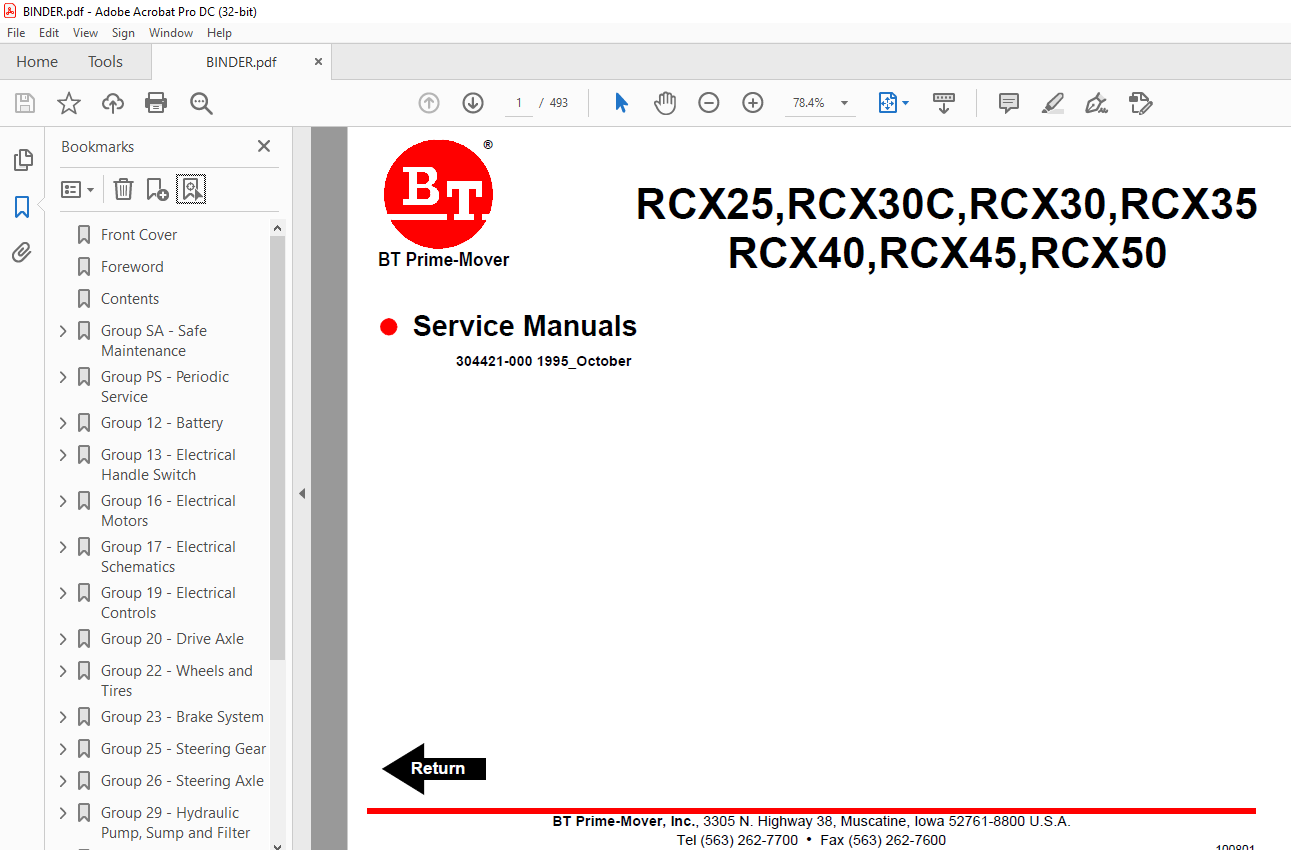
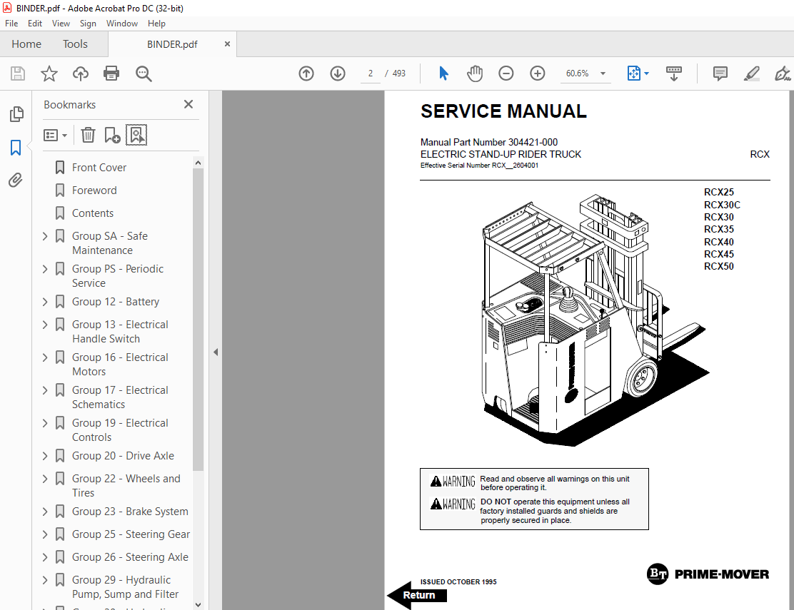
BT Prime-Mover Forklift ELECTRIC STAND-UP RIDER TRUCK SERVICE MANUAL – PDF DOWNLOAD
BT Prime-Mover Forklift ELECTRIC STAND-UP RIDER TRUCK SERVICE MANUAL – PDF DOWNLOAD
FILE DETAILS:
BT Prime-Mover Forklift ELECTRIC STAND-UP RIDER TRUCK SERVICE MANUAL – PDF DOWNLOAD
Language : English,
Pages :493
Downloadable : Yes
File Type : PDF
TABLE OF CONTENTS:
BT Prime-Mover Forklift ELECTRIC STAND-UP RIDER TRUCK SERVICE MANUAL – PDF DOWNLOAD
Front Cover 2
Foreword 4
Contents 6
Group SA – Safe Maintenance 10
Section 1 – Safety 12
Safety Signs and Messages 13
Safety Maintenance Practices 13
General Shop Precautions 15
Section 2 – Machine Jacking and Blocking 18
Raising Drive Wheels 19
Blocking the Upright in Raised Position 20
Raising Rear of Truck 20
Raising Truck with a Hoist 21
Group PS – Periodic Service 22
Section 1 – Maintenance Schedules 24
Maintenance Schedules 25
Lubrication Points 26
Lubrication Chart Key 27
Miscellaneous Lubricants 28
Section 2 – Planned Maintenance 30
Use PM Report Form 31
How to Perform the PM Periodic Inspections and Maintenance 31
Visual Inspection 31
Functional Checks 34
Test Drive Truck with Load 37
Lift Mechanism and Controls 38
Battery Compartment Inspection 39
Motor SCR Control Inspection 40
Control and Hydraulic Compartment Inspection 40
Control Levers and Linkage Inspection 40
Air Cleaning 40
Critical Fastener Torque Checks 40
Lubrication, Fluids and Filters 41
Hydraulic Sump 41
Hydraulic Fluid and Filter Change 41
Hydraulic Oil Filter 41
Sump Tank Breather Maintenance 41
Access to the Drive Axle 41
Drive Axle Fluid 41
Drive Axle Fluid Change 42
Truck Chassis Inspection and Lubrication 42
Uprights and Tilt Cylinder Lubrication 42
Lift Chains 42
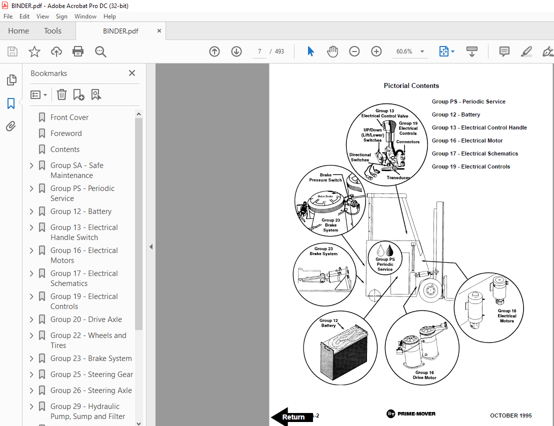
Group 12 – Battery 44
Section 1 – Battery Handling 46
Typical Battery Service Area 47
Battery Handling 48
Battery Maintenance 51
How to Get Maximum Life Out of Your Battery 51
Battery Vents 52
Battery Cleaning 52
Battery Charging 52
Battery Electrolyte 52
Clean Battery Compartment 52
Replacement Battery 52
Install Battery 53
Keeping Battery Records 53
Group 13 – Electrical Handle Switch 54
Section 1 – Control Handle Switch 56
Tilt, Auxiliary 1 and Auxiliary 2 (Attachment) Switches 59
Remove and Install 59
Up and Down Switches 60
Remove and Install 60
Forward and Reverse Switches, Transducer (Speed Control) 61
Remove and Install Switches 61
Remove and Install Transducer 61
Group 16 – Electrical Motors 62
Section 1 – General Information 64
Safety 65
Servicing Electric Motors 65
Electric Motor Maintenance 66
Inspection Procedures 66
Motor Cleanliness 66
Motor Inspection 66
Test for Motor Insulation “Resistance to Ground” 67
Using a 500 Volt Megger 67
Using a Simpson 260-6p Volt Ohmmeter or Equivalent Calibrated on the Rx 10,000 Scale 67
Brush and Commutator Inspection 68
Operating Conditions 68
Brush and Commutator Inspection 68
Brush Inspection Chart 70
Section 2 – Drive Motors 72
Safety 73
General Information 74
Operating Conditions 74
Drive Motor Description 75
Drive Motor Removal 75
Drive Motor 75
Drive Motor 77
Disassembly 77
Component Inspection and Troubleshooting 79
Testing 80
Frame and Field Service Notes 80
Assembly 80
36 Volt Drive Motor Specifications 82
Brush Inspection Chart 83
Section 3 – Hydraulic Pump Motors 84
Safety 85
General Information 86
Operating Conditions 86
Hydraulic Pump Motor 87
Disassembly 87
Component Inspection and Troubleshooting 89
Testing 90
Frame and Field Service Notes 90
Assembly 90
36 Volt Drive Motor Specifications 92
Brush Inspection Chart 93
Section 4 – Steer Pump Motor 94
Safety 95
General Information 96
Operating Conditions 96
Steer Pump Motor (Permanent Magnet Type) 97
Troubleshooting Prior to Disassembly 97
Disassembly 99
Component Inspection and Troubleshooting101
Assembly102
36 Volt Drive Motor Specifications103
Motor Specifications103
Brush Inspection Chart104
Group 17 – Electrical Schematics106
Section 1 – Wiring Schematics and Diagrams108
Standard Wiring Schematic109
Standard Wiring Diagram110
Optional Wiring Schematic111
Optional Wiring Diagram112
Lights Wiring Schematic113
Lights Wiring Diagram114
Strobe and Alarm Wiring Schematic115
Strobe and Alarm Wiring Diagram116
Group 19 – Electrical Controls118
Section 1 – Control Panel120
Control Panel Description121
Control Features123
Control Panel Maintenance124
Control Panel Troubleshooting124
Troubleshooting Notes125
Control and Contactor Panel Removal125
Control and Contactor Panel Component Identification127
Contactor Inspection131
1A and Main Pump Contactors131
Plugging and Power Steering Contactor133
Forward and Reverse Contactor134
Oscillator Card138
Control and Contactor Panel Installation139
Section 2 – EV-100MK Troubleshooting144
Check #1, 2, 5 REC’s (SCR’s)145
Check Capacitor (1C)149
Checking Component with VOM (Only)150
#22, 23, 24 and 25 Filter Blocks150
#3 and 4 Rectifiers151
Filter Mounting Terminal Block152
Sensor153
Thermal Protector154
Reactor/Choke Module155
EV-100 MK Card Factory Settings156
Oscillator Card Voltage Checks157
Oscillator Card Wiring Schematic158
Solenoid Function Control Card Voltage Checks159
Solenoid Function Control Card Wiring Schematic160
Section 3 – Recommended Tests, Equipment, and Procedures162
Recommended Tests163
Test Equipment163
Test Procedures163
Test Procedures163
Ground Fault Condition163
Power Steer Idle Current164
SCR Current Limit164
1A Free-Wheeling Current164
1A Time Delay165
Creep Speed Motor Volts165
Plugging166
Section 4 – Drive Motor Cut-Out Switch Check and Adjustment168
Drive Motor Cut-Out Switch Check169
Drive Motor Cut-Out Switch Adjustment170
Section 5 – Forward and Reverse Switches, Up and Down Switches, and Transducer Adjustments172
Multi-Function Control Handle Connector Identification173
Switches and Transducer Adjustments174
Section 6 – Periodic Electrical Checks184
Truck Preparation185
Electrical Connectors186
Power Cables188
Fasteners189
Motor Connections190
Control Panel Connections191
Cable Routing and Connections192
Control Cards Connections196
Section 7 – Battery Tests198
Battery Tests199
Section 8 – Solenoid Control Card Troubleshooting200
Indicator Lights201
Troubleshooting Solenoid Control Card202
Lift Function ONLY Disabled204
Install New Solenoid Control Card206
Section 14 – EV100 LXT Control Panel208
General209
Operation209
Function Set-Up Procedures210
Description of Function Numbers for:211
IC3645EVLXCDI1TT211
IC3645EVLXCDI1TX211
IC3645EVLXCDI1TK211
IC3645EVLXCDI1MT214
IC3645EVLXCDI1MX214
IC3645EVLXCDI1MK214
IC3645EVLXCDI1PX217
Section 15 – EV100 LXT Control Panel Status Codes220
Section 16 – Checking Components254
Main Logic Card255
Capacitor256
Contactors F, R, 1A, SP, FW, D, Regen, and P256
Potentiometer in Accelerator256
SCR’s (1REC, 2REC, 3REC)256
Rectifiers (3REC, 4REC, Diode Blocks)257
Thermal Protector (TP)257
Filter Block (23FIL, etc)257
1X Choke and Reactor T3-T4257
Replacement of EV-100 Components258
1REC, 2REC, or 5REC258
Capacitor258
22REC, 23REC, and 25REC258
Group 20 – Drive Axle260
Section 1 – Drive Axle262
General Description263
Service Notes263
Drive Axle Maintenance263
Fluid Level Checks263
Fluid Change Procedure263
Drive Axle Removal264
Drive Axle Special Tools265
Drive Axle Disassembly269
Drive Axle Notes269
Drive Axle Assembly272
Drive Axle Installation275
Group 22 – Wheels and Tires278
Section 1 – Cushion Wheels and Tires280
Cushion Drive and Steering Tire Specifications281
Cushion Drive Tire Removal281
Cushion Drive Tire Inspection281
Cushion Drive Tire Removal and Replacement282
Cushion Drive Wheel Installation282
Steering Wheel Removal283
Steering Tire Inspection284
Steering Wheel Installation284
Section 2 – Pneumatic Drive Tire and Wheel Maintenance286
Pneumatic Tire Warning287
Safety Procedures288
Pneumatic Drive Tire Specifications289
Pneumatic Tire Maintenance289
Pneumatic Drive Wheel and Tire Removal and Disassembly290
Pneumatic Drive Tire Assembly295
Filling Tires with Air295
Filling Tires with Nitrogen295
Procedures for Adding Air Pressure to Mounted Tire and Wheel Assembly297
Directional Thread Tires298
Pneumatic Drive Wheel and Tire Installation298
Group 23 – Brake System300
Section 1 – Brake System and Bleeding302
Brake System Description303
Bleeding the Brake System304
Section 2 – Brake Adjustment306
Brake Lining Wear Check307
Brake Lining Wear Adjustment308
Minor Brake Adjustment308
Major Brake Adjustment309
Replacing Brake Linings310
Section 3 – Brake Slave Cylinder312
Brake Slave Cylinder313
Removal313
Disassembly314
Inspection314
Assembly314
Installation315
Group 25 – Steering Gear316
Section 1 – Steering Gear318
Steering Gear Description319
Steering Gear Troubleshooting320
Steering Gear Removal320
Steering Gear Disassembly321
Steering Gear Parts Inspection323
Steering Gear Assembly323
Steering Gear Installation326
Group 26 – Steering Axle328
Section 1 – Steering Axle Repair330
Steering Axle Removal331
Steering Axle Installation332
Section 2 – Power Steering Pump334
Steering Pump Description335
Steering Pump Troubleshooting335
Steering Pump Removal335
Steering Pump Disassembly337
Steering Pump Parts Inspection338
Steering Pump Assembly339
Steering Pump Installation340
Steering Pump Installation Specifications341
Steering Lines Installation Specifications342
Reverse Steering Lines Installation Specifications344
Section 3 – Steering Torque Generator346
Steering Torque Generator Description347
Steering Torque Generator Removal347
Steering Torque Generator Disassembly349
Steering Torque Generator Parts Inspection350
Steering Torque Generator Assembly351
Steering Torque Generator Installation352
Steering Torque Generator Assembly Specifications354
Steering Torque Generator Lines Installation Specifications355
Group 29 – Hydraulic Pump, Sump and Filter356
Section 1 – Hydraulic Pump358
Main Hydraulic Pump359
Removal359
Preparation for Disassembly359
Disassembly359
Parts Inspection359
Assembly361
Hydraulic Pump Installation363
Hydraulic Pump Installation Specifications363
Section 2 – Hydraulic Sump and Filter364
Hydraulic Sump and Filter Assembly365
Section 3 – Hydraulic Schematics366
Hydraulic Diagram367
Group 30 – Hydraulic Control Valves368
Section 1 – Main Control Valve370
Servicing Main Control Valve371
Relief Valve Assembly373
Procedure for Cartridge Seal Replacement373
Adjustable Relief Valve Seal Nut Replacement374
Non-Adjustable Relief Valve374
Load Check Valve375
Disassembly375
Inspection375
Assembly375
Main Control Valve End Cap and Components376
Disassembly376
Assembly376
Main Control Valve378
Disassembly378
Assembly379
Section 2 – Face Seal Fittings380
Face Seal Fittings382
Assembly Suggestions382
Hydraulic Hose or Tube Installation382
Section 3 – Hydraulic System Pressure Checks – Lift Circuit384
Test Ports385
Hydraulic Lift Circuits Pressure Checks386
Check Lift Circuit Relief Valve Setting386
Relief Valve Adjustment386
Section 4 – Hydraulic System Pressure Checks – Steering Circuit388
Test Ports389
Hydraulic Steering Circuit Pressure Checks390
Check Steering Circuit Relief Valve Setting390
Relief Valve Adjustment390
Section 5 – Hydraulic System Pressure Checks – Auxiliary and Tilt Circuits392
Test Ports393
Hydraulic Pressure Checks394
Check Auxiliary and Tilt Circuits Relief Valve Setting394
Relief Valve Adjustment395
Section 6 – Flow Controls – Selector Solenoid Valve396
Valve Identification397
Hydraulic Solenoid Valves398
Cartridge Valve Installation Procedure398
Service Specifications399
Optional Auxiliary 2 Valve Specifications400
Group 31 – Hydraulic Supply System402
Section 1 – Hydraulic System404
General Description405
Hydraulic Fluid and Filter Change405
Remote Pump Method405
Truck Pump Method406
Hydraulic Sump Tank408
Group 32 – Cylinders410
Section 1 – Tilt Cylinder412
Tilt Cylinder Components413
Tilt Cylinder Plumbing Layout414
Tilt Cylinder Drift Test415
Tilt Cylinder Removal415
Tilt Cylinder Rod End Removal417
Tilt Cylinder Disassembly417
Tilt Cylinder Inspection417
Tilt Cylinder Assembly419
Tilt Cylinder Installation419
Face Seal Fittings421
Assembly Suggestions421
Tilt Check and Adjustment423
Group 33 – Selector Solenoid Valve426
Section 1 – Selector Solenoid Valve428
Selector Solenoid Valve Description429
Selector Solenoid Valve Troubleshooting429
Selector Solenoid Valve Removal430
Selector Solenoid Valve Repair430
Selector Solenoid Valve Installation430
Device Selector Solenoid Valve431
Group 34 – Uprights432
Section 1 – Upright434
Upright Maintenance435
Triple Stage Upright435
Upright Rail Shim Inspection435
Carriage Shim Inspection437
Disassembly for Shim Adjustments437
Assembly for Shim Adjustments443
Lift Cylinder Drift Check444
Hydraulic Cylinder Repair445
Standard (Two Stage) Upright447
Upright Rail Shim Inspection447
Carriage Shim Inspection449
Disassembly for Shim Adjustments449
Assembly for Shim Adjustment453
Lift Cylinder Drift Check454
Upright Cylinder Repair454
Section 2 – Chain Inspection, Adjustment, and Replacement460
Periodic Inspection463
Elongation463
Edge Wear463
Turning or Protruding Pins463
Cracked Plate463
Ultimate Strength Failure464
Tight Joints464
Chain Length Adjustments464
Standard Upright Chain Length Adjustments465
Triple-Stage Upright (TSU) Chain Length Adjustment465
Chain Lubrication467
Chain Removal and Replacement467
General Guidelines467
Lift Chains (Standard and TSUs)468
Carriage Chains (TSUs)468
Other Chain Service Notes469
Group 40 – Specifications470
Section 1 – Specifications472
Group 12 – Battery473
Group 16 – Motors474
Group 19 – Electrical Controls474
Group 20 – Drive Axle475
Group 22 – Wheels and Tires475
Group 23 – Brakes475
Group 25/26 – Steering System475
Group 29/30 – Hydraulic System475
Group 32 – Tilt Cylinder476
Group 34 – Uprights477
Group 40 – Specifications478
Section 2 – Data Plate480
How to Read Data Plate481
Battery Weight Chart483
Section 3 – Lubricants and Shop Supplies484
Lubricants and Shop Supplies485
Lubricants485
Sealants487
Gasket Materials488
Threadlocks and Threadsealers489
Cleaners490
Back Cover493
IMAGES PREVIEW OF THE MANUAL:
More products


