$38
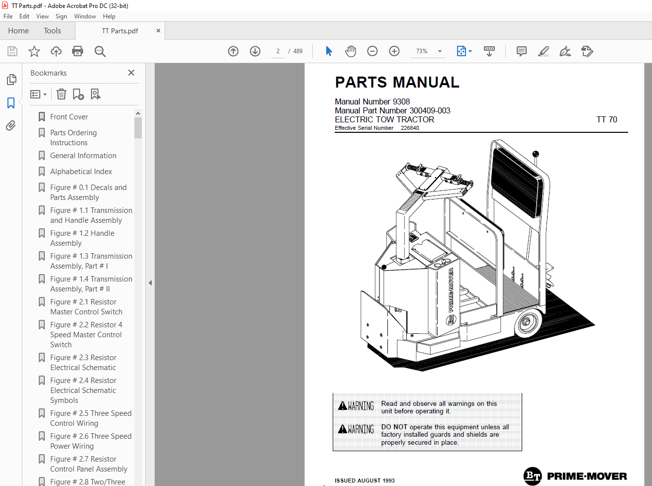
BT Prime-Mover Forklift ELECTRIC TOW TRACTOR PARTS MANUAL 9308 – PDF DOWNLOAD
BT Prime-Mover Forklift ELECTRIC TOW TRACTOR PARTS MANUAL 9308 – PDF DOWNLOAD
FILE DETAILS:
BT Prime-Mover Forklift ELECTRIC TOW TRACTOR PARTS MANUAL 9308 – PDF DOWNLOAD
Language : English,
Pages :489
Downloadable : Yes
File Type : PDF
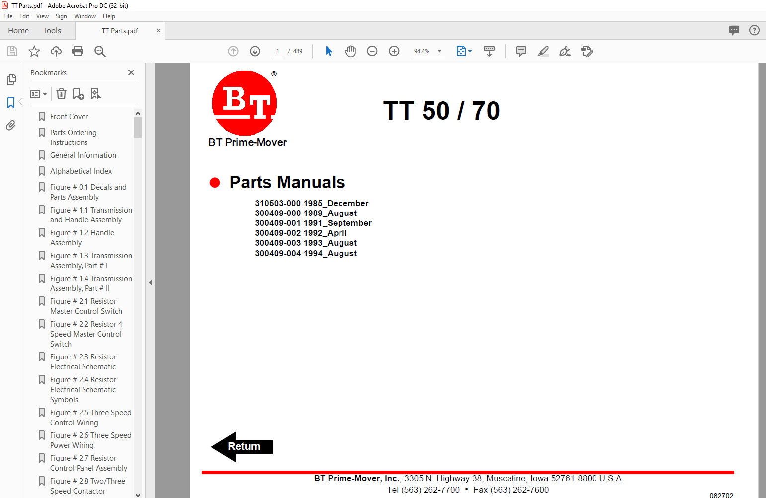
310503-000 1985_December
300409-000 1989_August
300409-001 1991_September
300409-002 1992_April
300409-003 1993_August
300409-004 1994_August
TABLE OF CONTENTS:
BT Prime-Mover Forklift ELECTRIC TOW TRACTOR PARTS MANUAL 9308 – PDF DOWNLOAD
Front Cover 2
Parts Ordering Instructions 3
General Information 4
Alphabetical Index 5
Figure # 01 Decals and Parts Assembly 7
Figure # 11 Transmission and Handle Assembly 9
Figure # 12 Handle Assembly 11
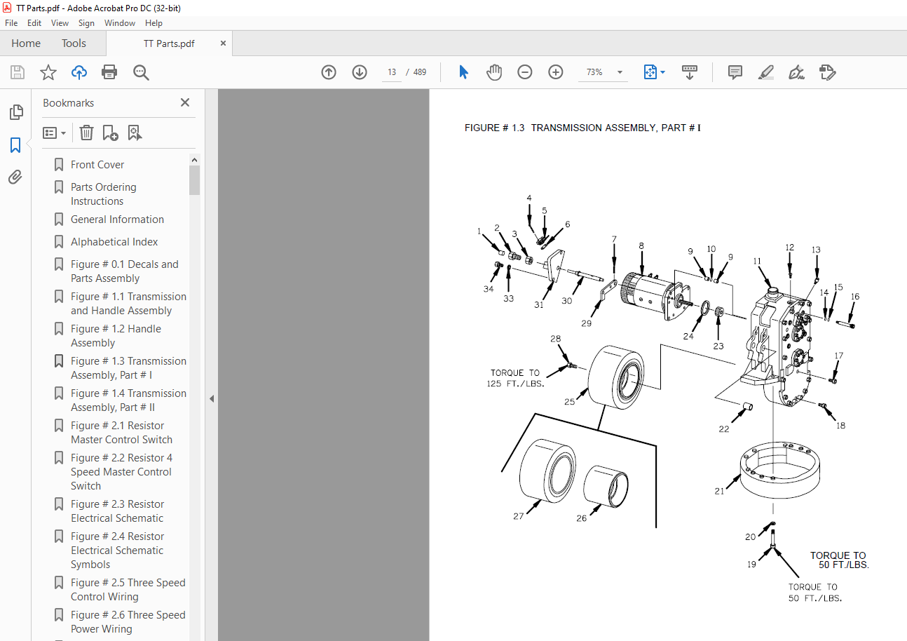
Figure # 13 Transmission Assembly, Part # I 13
Figure # 14 Transmission Assembly, Part # II 15
Figure # 21 Resistor Master Control Switch 17
Figure # 22 Resistor 4 Speed Master Control Switch 19
Figure # 23 Resistor Electrical Schematic 21
Figure # 24 Resistor Electrical Schematic Symbols 22
Figure # 25 Three Speed Control Wiring 23
Figure # 26 Three Speed Power Wiring 25
Figure # 27 Resistor Control Panel Assembly 27
Figure # 28 Two/Three Speed Contactor Assembly 29
Figure # 29 Forward & Rearward Contactor Assembly 31
Figure # 210 Three Speed Contactor Panel Assembly 33
Figure # 211 Fourth Speed Control Wiring 35
Figure # 212 Fourth Speed Power Component Wiring 37
Figure # 213 Fourth Speed Contactor Panel Assembly 39
Figure # 214 Contactor Assembly 41
Figure # 215 Transistor Electrical Schematic 43
Figure # 216 Transistor Electrical Schematic Symbols 44
Figure # 218 Transistor Control Wiring Assembly 45
Figure # 219 Transistor Contactor Panel Assembly 47
Figure # 220 Contactor Assembly 49
Figure # 221 Power Connector Assembly 51
Figure # 222 24 Volt Drive Motor Assembly 53
Figure # 223 Wiring Assembly for Cold Storage 55
Figure # 41 Cushion and Floor Mat Installation 57
Figure # 42 Shielding Installation 59
Figure # 43 Frame Assembly 61
Figure # 44 Automatic Coupler and Tow Eye Assembly 63
Figure # 101 Special Tools and Lubrications 65
Numerical Index 68
Back Cover 77
Front Cover 78
Parts Ordering Instructions 79
General Information 80
Alphabetical Index 81
Figure # 01 Decals and Parts Assembly 83
Figure # 11 Transmission and Handle Assembly 85
Figure # 12 Handle Assembly 87
Figure # 13 Transmission Assembly, Part # I 89
Figure # 14 Transmission Assembly, Part II 91
Figure # 21 Resistor Master Control Switch 93
Figure # 22 Resistor 4 Speed Master Control Switch 95
Figure # 23 Resistor Electrical Schematic 97
Figure # 24 Resistor Electrical Schematic Symbols 98
Figure # 25 Three Speed Control Wiring 99
Figure # 26 Three Speed Power Wiring101
Figure # 27 Resistor Control Panel Assembly103
Figure # 28 Two/Three Speed Contactor Assembly105
Figure # 29 Forward & Rearward Contactor Assembly107
Figure # 210 Three Speed Contactor Panel Assembly109
Figure # 211 Fourth Speed Control Wiring111
Figure # 212 Fourth Speed Power Component Wiring113
Figure # 213 Fourth Speed Contactor Panel Assembly115
Figure # 214 Contactor Assembly117
Figure # 215 Transistor Electrical Schematic119
Figure # 216 Transistor Electrical Schematic Symbols120
Figure # 217 Transistor Control Wiring Assembly121
Figure # 218 Transistor Power Component Wiring123
Figure # 219 Transistor Contactor Panel Assembly125
Figure # 220 Contactor Assembly127
Figure # 221 Power Connector Assembly129
Figure # 222 Drive Motor Assembly131
Figure # 223 Wiring Assembly for Cold Storage133
Figure # 41 Cushion and Floor Mat Installation135
Figure # 42 Shielding Installation137
Figure # 43 Frame Assembly139
Figure # 44 Automatic Coupler and Tow Eye Assembly141
Figure # 101 Special Tools and Lubrications143
Numerical Index146
Back Cover155
Front Cover156
Warranty157
Parts Ordering Instructions158
Field Modifications158
General Information159
Figure # 1 Decal and Parts Assembly161
Figure # 2 Parts List and Service Reference Index163
Figure # 3 Shield Assembly165
Figure # 4 Transmission and Handle Assembly167
Figure # 5 Tee Handle Assembly169
Figure # 6 Master Control Switch Assembly171
Figure # 7 TT-70 Fourth Speed Master Control Switch173
Figure # 8 TT-50 22:1 Transmission Assembly175
Figure # 9 TT-50 22:1 Drive Motor Assembly177
Figure # 10 TT-50 22:1 Drive Motor, 12 Volt179
Figure # 11 TT-70 14:1 Transmission Assembly181
Figure # 12 TT-70 14:1 Motor Assembly183
Figure # 13 TT-50 Electrical Schematic185
Figure # 14 TT-70 Electrical Schematic186
Figure # 15 Electrical Schematic Symbols187
Notes188
Figure # 16 TT-50 2 Speed Control Wiring Harness Assembly189
Figure # 17 TT-50 3 Speed Control Wiring Harness Assembly191
Figure # 18 TT-70 3 Speed Control Wiring Harness Assembly193
Figure # 19 TT-70 4 Speed Control Wiring Harness Assembly195
Figure # 20 TT-50 2 Speed Power Component Assembly197
Figure # 21 TT-50 3 Speed Power Component Assembly199
Figure # 22 TT-70 3 Speed Power Component Assembly201
Figure # 23 TT-70 4 Speed Power Component Assembly203
Figure # 24 TT-50 2 Speed Control Panel Assembly205
Figure # 25 GE Contactor Assembly207
Figure # 26 GE Contactor Assembly209
Figure # 27 TT-50 3 Speed and TT-70 Control Panel Assembly211
Figure # 28 3rd and 4th Speed Reverse Contactor Assembly213
Figure # 29 TT-50 Cableform 3rd Speed Panel Assembly215
Figure # 30 Contactor Assembly217
Figure # 31 TT-70 3rd Speed Panel Assembly219
Figure # 32 4th Speed Contactor Panel Assembly221
Figure # 33 Power Connector Assembly223
Figure # 34 Frame Assembly225
Figure # 35 Spring Loaded Caster Assembly227
Figure # 36 Automatic Coupler and Eye Tow Assembly229
Numerical Index231
Back Cover239
Front Cover240
Parts Ordering Instructions241
Alphabetical Index243
Figure # 01 Decals and Parts Assembly245
Figure # 02 Parts List and Index247
Figure # 11 TT-50 22:1 Transmission and Handle Assembly249
Figure # 12 TT-70 14:1 Transmission and Handle Assembly251
Figure # 13 Tee Handle Assembly253
Figure # 14 TT-50 22:1 Part # I Transmission Assembly255
Figure # 15 TT-50 22:1 Part # II Transmission Assembly257
Figure # 16 TT-50 22:1 Drive Motor Assembly259
Figure # 17 TT-70 14:1 Part # I Transmission Assembly261
Figure # 18 TT-70 14:1 Part # II Transmission Assembly263
Figure # 21 Resistor Master Control Switch265
Figure # 22 Resistor 4 Speed Master Control Switch267
Figure # 23 EV-100/EV-1 SCR Master Control Switch269
Figure # 24 TT-50 Resistor Electrical Schematic271
Figure # 25 Resistor Electrical Schematic Symbols272
Figure # 26 TT-50 Two/Three Speed Control Wiring, 12 Volt273
Figure # 27 TT-50 Two/Three Speed Power Component Wiring275
Figure # 28 TT-50 Resistor Control Panel Assembly, 12 Volt277
Figure # 29 TT-50 Two Speed Contactor Assembly, 12 Volt279
Figure # 210 TT-50 Forward & Rearward Contactor Assembly, 12 Volt281
Figure # 211 TT-50 Three Speed Contactor Panel Assembly, 12 Volt283
Figure # 212 TT-50 Three Speed Contactor Assembly285
Figure # 213 TT-70 Resistor Electrical Schematic287
Figure # 214 Resistor Electrical Schematic Symbols288
Figure # 215 TT-70 Three Speed Control Wiring, 24 Volt289
Figure # 216 TT-70 Three Speed Power Component Wiring291
Figure # 217 TT-70 Resistor Control Panel Assembly, 24 Volt293
Figure # 218 TT-70 Two/Three Speed Contactor Assembly, 24 Volt295
Figure # 219 TT-70 Forward & Rearward Contactor Assembly, 24 Volt297
Figure # 220 TT-70 Three Speed Contactor Panel Assembly, 24 Volt299
Figure # 221 TT-70 Fourth Speed Control Wiring, 24 Volt301
Figure # 222 TT-70 Fourth Speed Power Component Wiring, 24 Volt303
Figure # 223 TT-70 Fourth Speed Contactor Panel Assembly305
Figure # 224 Contactor Assembly (Cableform), 24 Volt307
Figure # 225 TT-70 EV-100 SCR Trucks Electrical Schematic309
Figure # 226 TT-70 EV-100 SCR Truck Electrical Schematic Symbols310
Figure # 227 TT-70 EV-100 SCR Two/Three Speed Control Wiring311
Figure # 228 TT-70 EV-100 SCR Two Speed Power Component Wiring313
Figure # 229 TT-70 EV-100 SCR Contactor Panel Assembly315
Figure # 230 TT-70 EV-100 SCR Forward & Rearward Contactor Assembly317
Figure # 231 TT-70 EV-100 1A Contactor Assembly319
Figure # 232 TT-70 EV-100 SCR Two Speed Panel Assembly321
Figure # 233 TT-70 EV-100 SCR Three Speed Power Component Wiring323
Figure # 234 TT-70 EV-100 SCR Three Speed Contactor Panel Assembly325
Figure # 235 TT-70 EV-100 SCR Two/Three Speed Control Panel327
Figure # 236 Power Connector Assembly329
Figure # 237 TT-50 22:1 Drive Motor Assembly, 12 Volt331
Figure # 238 TT-70 14:1 Drive Motor Assembly333
Figure # 239 Wiring Assembly for Cold Storage335
Figure # 41 Cushion and Floor Mat Installation337
Figure # 42 Shielding Assembly339
Figure # 43 Frame Assembly341
Figure # 44 Automatic Coupler and Tow Eye Assembly343
Figure # 61 Special Tools and Lubrications345
Numerical Index348
Back Cover363
Front Cover364
Parts Ordering Instructions365
General Information366
Alphabetical Index367
Figure # 01 Decals and Parts Assembly371
Figure # 11 TT-50 22:1 Transmission and Handle Assembly373
Figure # 12 TT-70 14:1 Transmission and Handle Assembly375
Figure # 13 Tee Handle Assembly377
Figure # 14 TT-50 22:1 Transmission Assembly, Part # I379
Figure # 15 TT-50 22:1 Transmission Assembly, Part # II381
Figure # 16 TT-50 22:1 Drive Motor Assembly383
Figure # 17 TT-70 14:1 Transmission Assembly, Part # I385
Figure # 18 TT-70 14:1 Transmission Assembly, Part II387
Figure # 21 Resistor Master Control Switch389
Figure # 22 Resistor 4 Speed Master Control Switch391
Figure # 23 EV-100 SCR Master Control Switch393
Figure # 24 TT-50 Resistor Electrical Schematic395
Figure # 25 TT-50 Resistor Electrical Schematic Symbols396
Figure # 26 TT-50 Two/Three Speed Control Wiring397
Figure # 27 TT-50 Two/Three Speed Power Component Wiring399
Figure # 28 TT-50 Resistor Control Panel Assembly, 12 Volt401
Figure # 29 TT-50 Two Speed Contactor Assembly, 12 Volt403
Figure # 210 TT-50 Forward & Rearward Contactor Assembly, 12 Volt405
Figure # 211 TT-50 Three Speed Contactor Panel Assembly, 12 Volt407
Figure # 212 TT-50 Three Speed Contactor Assembly, 12 Volt409
Figure # 213 TT-70 Resistor Electrical Schematic411
Figure # 214 TT-70 Resistor Electrical Schematic Symbols412
Figure # 215 TE-70 Three Speed Control Wiring, 24 Volt413
Figure # 216 TT-70 Three Speed Power Wiring415
Figure # 217 TT-70 Resistor Control Panel Assembly, 24 Volt417
Figure # 218 TT-70 Three Speed Contactor Assembly, 24 Volt419
Figure # 219 TT-70 Forward & Rearward Contactor Assembly, 24 Volt421
Figure # 220 TT-70 Three Speed Contactor Panel Assembly, 24 Volt423
Figure # 221 TT-70 Fourth Speed Control Wiring, 24 Volt425
Figure # 222 TT-70 Fourth Speed Power Component Wiring, 24 Volt427
Figure # 223 TT-70 Fourth Speed Contactor Panel Assembly429
Figure # 224 TT-70 Contactor Assembly, 24 Volt431
Figure # 225 TT-70 EV-100 SCR Electrical Schematic433
Figure # 226 TT-70 EV-100 SCR Electrical Schematic Symbols434
Figure # 227 TT-70 EV-100 SCR Two/Three Speed Control Wiring435
Figure # 228 TT-70 EV-100 SCR Two Speed Power Component Wiring437
Figure # 229 TT-70 EV-100 SCR Contactor Panel Assembly439
Figure # 230 TT-70 EV-100 SCR Forward & Rearward Contactor Assembly441
Figure # 231 TT-70 EV-100 SCR 1A Contactor Assembly443
Figure # 232 TT-70 EV-100 SCR Two Speed Panel Assembly445
Figure # 233 TT-70 EV-100 SCR Three Speed Power Component Wiring447
Figure # 234 TT-70 EV-100 SCR Three Speed Contactor Panel Assembly449
Figure # 235 TT-70 EV-100 SCR Two/Three Speed Control Panel451
Figure # 236 Resistor Power Connector Assembly453
Figure # 237 TT-50 22:1 Two Speed (Only) Drive Motor Assembly, 12 Volt455
Figure # 238 TT-50 22:1 Two or Three Speed Drive Motor Assembly, 12 Volt457
Figure # 239 TT-70 14:1 Drive Motor Assembly, 24 Volt459
Figure # 240 Wiring Assembly for Cold Storage461
Figure # 41 Cushion and Floor Mat Installation463
Figure # 42 Shielding Assembly465
Figure # 43 Frame Assembly467
Figure # 44 Automatic Coupler and Tow Eye Assembly469
Figure # 71 Battery Travel Interrupt Installation471
Figure # 101 Special Tools and Lubrications473
Numerical Index476
Back Cover489
IMAGES PREVIEW OF THE MANUAL:
More products