$29
BT Prime-Mover Forklift PX40/PX40R ELECTRIC PALLET TRUCKS Parts Manual – PDF DOWNLOAD
BT Prime-Mover Forklift PX40/PX40R ELECTRIC PALLET TRUCKS Parts Manual – PDF DOWNLOAD
FILE DETAILS:
BT Prime-Mover Forklift PX40/PX40R ELECTRIC PALLET TRUCKS Parts Manual – PDF DOWNLOAD
Language : English,
Pages :95
Downloadable : Yes
File Type : PDF
TABLE OF CONTENTS:
BT Prime-Mover Forklift PX40/PX40R ELECTRIC PALLET TRUCKS Parts Manual – PDF DOWNLOAD
Front Cover 2
Warranty 3
Operating Instructions 5
Periodic Maintenance Chart 6
Maintenance Instructions 7
Service and Disassembly Instructions11
Parts Ordering Instructions12
Major Components13
Parts List Index14
Carrier Frame Components15
Lift Frame Linkage16
22:1 Spur Gear Transmission17
Drive Motor19
Electrical Schematic21
Control Wiring22
Power Wiring Assembly23
Electrical Control Panel24
Square D Forward/Reverse and 2nd Speed Contactors25
Handle – Lower Assembly26
Control Handle (Upper)27
Hydraulic Piping29
Hydraulic Cylinder30
Hydraulic Pump Parts31
Motor Parts33
Service Guide35
Back Cover37
Front Cover38
Warranty39
To New Owners40
Contents40
Preliminary Service40
Operation Instructions40
Operating Rules and Instructions41
Periodic Maintenance Chart45
Lubrications Chart46
Maintenance Instructions47
Service and Disassembly Instructions49
Parts Ordering Instructions57
Truck Specifications58
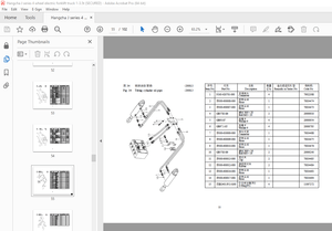
Figure # 1 Decal and Parts Assembly59
Figure # 2 Parts List and Service Reference Index60
Figure # 3 Shielding Assembly61
Figure # 4 Carrier Frame Assembly62
Figure # 5 Handle and Transmission Assembly63
Figure # 6 Handle Assembly64
Figure # 7 Master Control Switch65
Figure # 8 22:1 Transmission Assembly Part # 166
Figure # 9 22:1 Transmission Assembly Part # 267
Figure # 10 Drive Motor Assembly68
Figure # 11 12 Volt Drive Motor Assembly69
Figure # 12 Multiple Disc Brake Assembly70
Figure # 13 Drive Motor Assembly71
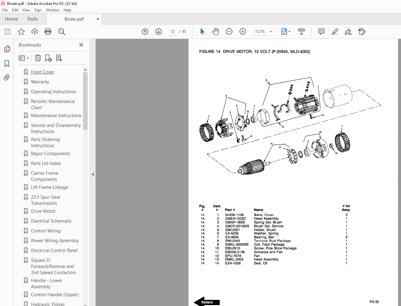
Figure # 14 Drive Motor, 12 Volt72
Figure # 15 Electrical Schematic73
Figure # 16 Electrical Schematic Symbols74
Figure # 17 Control Wiring Harness Assembly75
Figure # 18 Riding Control Wiring76
Figure # 19 Power Component Assembly77
Figure # 20 SB Type Connector Assembly78
Figure # 21 Control Panel Assembly79
Figure # 22 GE Contactor Assembly80
Figure # 23 GE Contactor Assembly81
Figure # 24 Cableform 3rd Speed Panel Assembly82
Figure # 25 Contactor Assembly (Cableform)83
Figure # 26 Hydraulic Schematic84
Figure # 27 Hydraulic Schematic Symbols84
Figure # 28 Hydraulic System85
Figure # 29 Cylinder Assembly86
Figure # 30 Hydraulic Pump and Motor Assembly87
Figure # 31 Motor Assembly88
Figure # 32 Lift Frame and Carrier Frame Assembly89
Figure # 33 Lift Frame Linkage90
Service Guide92
Back Cover95
IMAGES PREVIEW OF THE MANUAL:
More products