$41
BT Prime-Mover Forklift RS-50B ELECTRIC STRADDLE TRUCK PARTS MANUAL- PDF DOWNLOAD
BT Prime-Mover Forklift RS-50B ELECTRIC STRADDLE TRUCK PARTS MANUAL- PDF DOWNLOAD
FILE DETAILS:
BT Prime-Mover Forklift RS-50B ELECTRIC STRADDLE TRUCK PARTS MANUAL- PDF DOWNLOAD
Language : English,
Pages :1050
Downloadable : Yes
File Type : PDF
TABLE OF CONTENTS:
BT Prime-Mover Forklift RS-50B ELECTRIC STRADDLE TRUCK PARTS MANUAL- PDF DOWNLOAD
Front Cover 1
Parts Odering Instructions 2
General Information 3
Aphabetical Index 4
Group 70 402
Group 70 654
Numerical Index 667
Back Cover 688
Group 50 689
Front Cover 703
Parts Ordering Instructions 704
How to Order 704
Where to Order 704
Instructions for Returning Parts 704
Field Modifications 704
General Information 705
Alphabetical Index 706
Figure # 1 Decal and Parts Assembly 708
Figure # 2 Parts List and Service Reference Index 710
Figure # 3 Shielding Assembly 712
Figure # 4 Emergency Disconnect Assembly 714
Figure # 5 Auxiliary Control Assembly 716
Figure # 6 Hand Lift/Lower and Speed Control 718
Figure # 7 Master Control Switch 720
Figure # 8 Brake Linkage and Cylinder Assembly 722
Figure # 9 Brake Master Cylinder 724
Figure # 10 Drive Motor Brake Cylinder 726
Figure # 11 Idler Wheel Brake Cylinder 728
Figure # 12 Steering Control Assembly 730
Figure # 13 Auxiliary Pump Assembly 732
Figure # 14 Auxiliary Motor Assembly 734
Figure # 15 Transmission and Steering Installation 736
Figure # 16 Drive Motor and Brake Assembly 738
Figure # 17 Drive Motor Assembly 740
Figure # 18 Transmission Assembly Part # I 742
Figure # 19 Transmission Assembly Part # II 744
Figure # 20 Idler Wheel Installation 746
Figure # 21 Idler Wheel Assembly 748
Figure # 22 EV-100 Electrical Schematic 750
Figure # 23 Electrical Schematic Symbols 751
Figure # 24 Wiring Assembly for Cold Storage 752
Figure # 25 Wiring Harness Assembly 754
Figure # 26 Limit Switch Wiring Harness Assembly 756
Figure # 27 Two Stage Mast Cable Assembly 758
Figure # 28 Three Stage Mast Cable Assembly 760
Figure # 29 Tilt with Sideshifter Cable Assembly 762
Figure # 30 Power Component Wiring 764
Figure # 31 EV-100 SCR Contactor Panel Assembly 766
Figure # 32 EV-100 SCR Control 768
Figure # 33 EV-100 Forward & Rearward Contactor Assembly 770
Figure # 34 EV-100 Lift Pump(s) and 1A Contactor Assembly 772
Figure # 35 EV-100 Steering Contactor Assembly 774
Figure # 36 Connector Assembly 776
Figure # 37 Warning Light Assembly 778
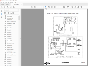
Figure # 38 Hydraulic Schematic 780
Figure # 39 Hydraulic Schematic Symbols 781
Figure # 40 Auxiliary Pump and Reservoir Assembly 782
Figure # 41 Auxiliary Control Valve Assembly 784
Figure # 42 Hydraulic Reservoir Assembly 786
Figure # 43 Steering Control Valve and Hose Assembly 788
Figure # 44 Steering Control Valve Assembly 790
Figure # 45 Steering Cylinder Assembly 792
Figure # 46 Two Stage Mast Hydraulic Assembly 794
Figure # 47 Three Stage Mast Hydraulic Assembly 796
Figure # 48 Tilt Cylinder and Related Parts 798
Figure # 49 Tilt Cylinder Assembly 800
Figure # 50 Sideshifter Cylinder with Tilt Assembly 802
Figure # 51 Sideshifter Cylinder Assembly 804
Figure # 52 Sideshifter Manifold Valve Assembly 806
Figure # 53 Lift Pump and Reservoir Assembly 808
Figure # 54 Lift Pump and Motor Assembly 810
Figure # 541 Lift Pump and Motor Assembly 812
Figure # 55 24 Volt Lift Pump Assembly 814
Figure # 56 36 Volt Lift Pump Assembly 816
Figure # 57 Lift Motor Assembly 818
Figure # 58 Lift Control Valve Assembly 820
Figure # 59 Two Stage Cylinder and Reservoir Assembly 822
Figure # 60 Two Stage Cylinder Assembly 824
Figure # 61 Three Stage Cylinder and Reservoir Assembly 826
Figure # 62 Three Stage Staging Cylinder Assembly 828
Figure # 63 Three Stage Freelift Cylinder Assembly 830
Figure # 64 Two Stage Mast Installation 832
Figure # 65 Two Stage Inner Column Assembly 834
Figure # 66 Two Stage Outer Column Assembly 836
Figure # 67 Two Stage Cylinder Installation 838
Figure # 68 Lift Frame Assembly 840
Figure # 69 Sideshifter Assembly 842
Figure # 70 Fork Assembly 844
Figure # 71 Three Stage Mast Installation 846
Figure # 72 Three Stage Outer Column Assembly 848
Figure # 73 Three Stage Intermediate Column Assembly 850
Figure # 74 Three Stage Inner Column Assembly 852
Figure # 75 Three Stage Freelift Cylinder Installation 854
Figure # 76 Main Frame and Load Wheel Assembly 856
Figure # 77 Single Load Wheel Assembly 858
Figure # 78 5" High Articulating Load Wheel Assembly 860
Figure # 79 4" High Articulating Load Wheel Assembly 862
Figure # 80 Special Tools and Lubrications 864
Back Cover 868
Front Cover 869
Parts Ordering Instructions 870
General Information 871
Alphabetical Index 872
Figure # 1 Decal and Parts Assembly 874
Figure # 2 Parts List and Service Reference Index 876
Figure # 3 Shielding Assembly 878
Figure # 4 Emergency Disconnect Assembly 880
Figure # 5 Auxiliary Control Assembly 882
Figure # 6 Hand Lift/Lower and Speed Control 884
Figure # 7 Master Control Switch 886
Figure # 8 Brake Linkage and Cylinder Assembly 888
Figure # 9 Brake Master Cylinder 890
Figure # 10 Drive Motor Brake Cylinder 892
Figure # 11 Idler Wheel Brake Cylinder 894
Figure # 12 Steering Control Assembly 896
Figure # 13 Auxiliary Pump Assembly 898
Figure # 14 Auxiliary Motor Assembly 900
Figure # 15 Transmission and Steering Installation 902
Figure # 16 Drive Motor and Brake Assembly 904
Figure # 17 Drive Motor Assembly 906
Figure # 18 Transmission Assembly Part # 1 908
Figure # 19 Transmission Assembly Part # 2 910
Figure # 20 Idler Wheel Installation 912
Figure # 21 Idler Wheel Assembly 914
Figure # 22 EV-100 Electrical Schematic 916
Figure # 23 Electrical Schematic Symbols 917
Figure # 24 Wiring Assembly for Cold Storage 918
Figure # 25 Wiring Harness Assembly 920
Figure # 26 Limit Switch Wiring Harness Assembly 922
Figure # 27 Two Stage Mast Cable Assembly 924
Figure # 28 Three Stage Mast Cable Assembly 926
Figure # 29 Tilt with Sideshifter Cable Assembly 928
Figure # 30 Power Component Wiring 930
Figure # 31 EV-100 SCR Contactor Panel Assembly 932
Figure # 32 EV-100 SCR Control 934
Figure # 33 EV-100 Forward & Rearward Contactor Assembly 936
Figure # 34 EV-100 Lift Pumps and 1A Contactor Assembly 938
Figure # 35 EV-100 Steering Contactor Assembly 940
Figure # 36 Connector Assembly 942
Figure # 37 Warning Light Assembly 944
Figure # 38 Hydraulic Schematic 946
Figure # 39 Hydraulic Schematic Symbols 947
Figure # 40 Auxiliary Pump and Reservoir Assembly 948
Figure # 41 Auxiliary Control Valve Assembly 950
Figure # 42 Hydraulic Reservoir Assembly 952
Figure # 43 Steering Control Valve and Hose Assembly 954
Figure # 44 Steering Control Valve Assembly 956
Figure # 45 Steering Cylinder Assembly 958
Figure # 46 Two Stage Mast Hydraulic Assembly 960
Figure # 47 Three Stage Mast Hydraulic Assembly 962
Figure # 48 Tilt Cylinder and Related Parts 964
Figure # 49 Tilt Cylinder Assembly 966
Figure # 50 Sideshifter Cylinder with Tilt Assembly 968
Figure # 51 Sideshifter Cylinder Assembly 970
Figure # 52 Sideshifter Manifold Valve Assembly 972
Figure # 53 Lift Pump and Reservoir Assembly 974
Figure # 54 Lift Pump and Motor Assembly 976
Figure # 541 Lift Pump and Motor Assembly 978
Figure # 55 24 Volt Lift Pump Assembly 980
Figure # 56 36 Volt Lift Pump Assembly 982
Figure # 57 Lift Motor Assembly 984
Figure # 58 Lift Control Valve Assembly 986
Figure # 59 Two Stage Cylinder and Reservoir Assembly 988
Figure # 60 Two Stage Cylinder Assembly 990
Figure # 61 Three Stage Cylinder and Reservoir Assembly 992
Figure # 62 Three Stage Staging Cylinder Assembly 994
Figure # 63 Three Stage Freelift Cylinder Assembly 996
Figure # 64 Two Stage Mast Installation 998
Figure # 65 Two Stage Inner Column Assembly1000
Figure # 66 Two Stage Outer Column Assembly1002
Figure # 67 Two Stage Cylinder Installation1004
Figure # 68 Lift Frame Assembly1006
Figure # 69 Sideshifter Assembly1008
Figure # 70 Fork Assembly1010
Figure # 71 Three Stage Mast Installation1012
Figure # 72 Three Stage Outer Column Assembly1014
Figure # 73 Three Stage Intermediate Column Assembly1016
Figure # 74 Three Stage Inner Column Assembly1018
Figure # 75 Three Stage Freelift Cylinder Installation1020
Figure # 76 Main Frame and Load Wheel Assembly1022
Figure # 77 Single Load Wheel Assembly1024
Figure # 78 5" High Articulating Load Wheel Assembly1026
Figure # 79 4" High Articulating Load Wheel1028
Figure # 80 Special Tools and Lubrications1030
Numerical Index1032
Back Cover1050
IMAGES PREVIEW OF THE MANUAL:
More products