$28
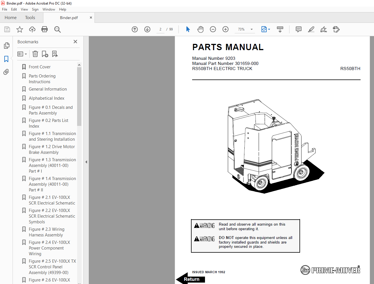
BT Prime-Mover Forklift RS50BTH Parts Manual – PDF DOWNLOAD
BT Prime-Mover Forklift RS50BTH Parts Manual – PDF DOWNLOAD
FILE DETAILS:
BT Prime-Mover Forklift RS50BTH Parts Manual – PDF DOWNLOAD
Language : English,
Pages :99
Downloadable : Yes
File Type : PDF
TABLE OF CONTENTS:
BT Prime-Mover Forklift RS50BTH Parts Manual – PDF DOWNLOAD
Front Cover 2
Parts Ordering Instructions 3
General Information 4
Alphabetical Index 5
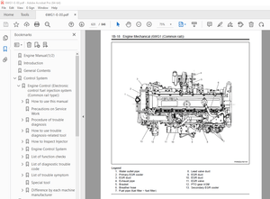
Figure # 01 Decals and Parts Assembly 7
Figure # 02 Parts List Index 9
Figure # 11 Transmission and Steering Installation11
Figure # 12 Drive Motor Brake Assembly13
Figure # 13 Transmission Assembly (40011-00) Part # I15
Figure # 14 Transmission Assembly (40011-00) Part # II17
Figure # 21 EV-100LX SCR Electrical Schematic19
Figure # 22 EV-100LX SCR Electrical Schematic Symbols20
Figure # 23 Wiring Harness Assembly21
Figure # 24 EV-100LX Power Component Wiring23
Figure # 25 EV-100LX TX SCR Control Panel Assembly (49399-00)25
Figure # 26 EV-100LX Contactor Panel Assembly & Related Parts27
Figure # 27 EV-100LX Contactor Panel Assembly (41757-01)29
Figure # 28 EV-100LX SCR Forward & Rearward Contactor Assembly (27692-00)31
Figure # 29 EV-100LX SCR 1A Contactor Assembly (27693-02)33
Figure # 210 EV-100LX SCR Auxiliary Pump Contactor Assembly (300073-000)35
Figure # 211 Power Connector Assembly (24 Volt, 49855-24)37
Figure # 212 Drive Motor Assembly, (27901-00, 5BT1326B235) GE39
Figure # 213 Auxiliary Pump Motor Assembly (300666-000, D-561371X8015A, OHIO)41
Figure # 31 Hydraulic Schematic43
Figure # 32 Hydraulic Schematic Symbols44
Figure # 33 Auxiliary Pump and Reservoir Assembly45
Figure # 34 Auxiliary Control Valve Assembly (41331-00)47
Figure # 35 Auxiliary Pump and Motor Assembly (300333-000)49
Figure # 36 Auxiliary Pump Assembly51
Figure # 37 Hydraulic Reservoir Assembly53
Figure # 38 Steering Control Valve Assembly (40102-01)55
Figure # 39 Steering Control Valve and Hose Assembly57
Figure # 310 Steering Cylinder Assembly (41544-00)59
Figure # 311 Clamp Cylinder and Related Parts61
Figure # 312 Clamp Cylinder Assembly (41228-00)63
Figure # 313 Brake Linkage and Cylinder Assembly65
Figure # 314 Brake Master Cylinder (41336-00)67
Figure # 315 Drive Motor Brake Cylinder (41337-00)69
Figure # 316 Idler Wheel Brake Cylinder (41338-00)71
Figure # 41 Shielding Assembly73
Figure # 42 Emergency Disconnect Assembly75
Figure # 43 Hand Clamp and Speed Control77
Figure # 44 Steering Control Assembly79
Figure # 45 Idler Wheel Installation81
Figure # 46 Idler Wheel Assembly83
Figure # 47 Main Frame and Load Wheel Assembly85
Figure # 101 Special Tools and Lubrications87
Numerical Index90
Back Cover99
IMAGES PREVIEW OF THE MANUAL:
More products