$38
BT Prime-Mover Forklift SR30 Parts Manual – PDF DOWNLOAD
BT Prime-Mover Forklift SR30 Parts Manual – PDF DOWNLOAD
FILE DETAILS:
BT Prime-Mover Forklift SR30 Parts Manual – PDF DOWNLOAD
Language : English,
Pages :433
Downloadable : Yes
File Type : PDF
TABLE OF CONTENTS:
BT Prime-Mover Forklift SR30 Parts Manual – PDF DOWNLOAD
Front Cover 2
Parts Ordering Instructions 3
General Information 4
Alphabetical Index 5
Numerical Index100
Back Cover109
Front Cover110
Parts Ordering Instructions111
General Information112
Alphabetical Index113
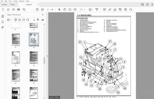
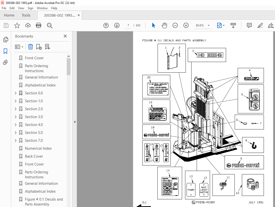
Figure # 01 Decals and Parts Assembly115
Figure # 02 Parts List Index117
Figure # 11 Transmission and Handle Assembly121
Figure # 12 Standard Control Handle Assembly123
Figure # 13 Thumb Control Handle Assembly125
Figure # 14 Transmission Assembly, Part # 1127
Figure # 15 Transmission Assembly, Part 2129
Figure # 16 Drive Motor Assembly131
Figure # 21 Resistor Electrical Schematic133
Figure # 22 Resistor Electrical Schematic Symbols134
Figure # 23 Resistor Control Wiring Harness Assembly135
Figure # 24 Resistor Power Component Wiring137
Figure # 25 Resistor Control Panel Assembly139
Figure # 27 Forward & Rearward Contactor Assembly141
Figure # 28 Power Connector Assembly143
Figure # 29 Drive Motor Assembly145
Figure # 210 Pump Motor Assembly147
Figure # 211 Warning Light Assembly149
Figure # 31 Two Stage Hydraulic Schematic151
Figure # 32 Two Stage Hydraulic Schematic Symbols152
Figure # 33 Two Stage Hydraulic System – Part # 1153
Figure # 34 Two Stage Hydraulic System – Part # 2155
Figure # 35 Two Stage Lift Cylinder and Related Parts157
Figure # 36 Two & Three Spool Control Valve Assembly159
Figure # 37 Two Stage Mast Lift Pump and Motor Assembly161
Figure # 38 Two Stage Lift Pump Assembly163
Figure # 39 Two Stage Hydraulic Reservoir Assembly165
Figure # 310 Two Stage Lift Cylinder Assembly167
Figure # 311 Two Stage Mast Hose Reel and Related Parts169
Figure # 312 Two Stage Mast Dual Elbow Swivel Assembly171
Figure # 313 Two Stage Mast Gleason Hose Reel Assembly173
Figure # 314 Two Stage Reach without Tilt Hose Assembly175
Figure # 315 Two Stage Mast Reach Cylinder Assembly177
Figure # 316 Two Stage Reach with Tilt Hose Assembly179
Figure # 317 Two Stage Mast Tilt Cylinder Assembly181
Figure # 318 Three Stage Mast Hydraulic Schematic183
Figure # 319 Three Stage Mast Hydraulic Schematic Symbols184
Figure # 320 Three Stage Hydraulic System – Part # 1185
Figure # 321 Three Stage Hydraulic System – Part # 2187
Figure # 322 Three Stage Lift Cylinders and Related Parts189
Figure # 323 Two & Three Spool Control Valve Assembly191
Figure # 324 Three Stage Mast Lift Pump and Motor Assembly193
Figure # 325 Three Stage Lift Pump Assembly195
Figure # 326 Three Stage Hydraulic Reservoir Assembly197
Figure # 327 Three Stage Staging Cylinder Assembly199
Figure # 328 Three Stage Freelift Cylinder Assembly201
Figure # 329 Three Stage Mast Hose Reel and Related Parts203
Figure # 330 Three Stage Mast Dual Elbow Swivel Assembly205
Figure # 331 Three Stage Mast Gleason Hose Reel Assembly207
Figure # 332 Three Stage Reach without Tilt Hose Assembly209
Figure # 333 Three Stage Mast Reach Cylinder Assembly211
Figure # 334 Three Stage Reach with Tilt Hose Assembly213
Figure # 335 Three Stage Mast Tilt Cylinder Assembly215
Figure # 41 Shielding Assembly217
Figure # 42 Main Frame and Load Wheel Installation219
Figure # 43 Caster Assembly221
Figure # 44 Two & Three Spool Control Valve Mounting Assembly223
Figure # 51 Two Stage Mast Installation225
Figure # 52 Two Stage Mast Outer Column Assembly227
Figure # 53 Two Stage Mast Inner Column Assembly229
Figure # 54 Two Stage Mast Cylinder and Related Parts231
Figure # 55 Two Stage Mast Lift Frame Assembly233
Figure # 56 Three Stage Reach Assembly235
Figure # 57 Two Stage Mast Reach Assembly237
Figure # 58 Two Stage Fork Assembly239
Figure # 59 Three Stage Mast Installation241
Figure # 510 Three Stage Mast Outer Column Assembly243
Figure # 511 Three Stage Mast Intermediate Column Assembly245
Figure # 512 Three Stage Mast Inner Column Assembly247
Figure # 513 Three Stage Mast Freelift Cylinder Installation249
Figure # 514 Three Stage Mast Lift Frame Assembly251
Figure # 515 Three Stage Reach Assembly253
Figure # 516 Three Stage Mast Reach Assembly255
Figure # 517 Three Stage Fork Assembly257
Figure # 71 Special Tools and Lubrications259
Back Cover261
Front Cover262
Parts Ordering Instructions263
General Information264
Alphabetical Index265
Section 00267
Figure # 01 Decals and Parts Assembly267
Section 10269
Figure # 11 Transmission and Handle Assembly269
Figure # 12 Twist Grip Resistor/Transistor Control Handle Assembly271
Figure # 13 Thumb Control Resistor/Transistor Control Handle Assembly273
Figure # 14 Transmission Assembly, Part # 1275
Figure # 15 Transmission Assembly, Part # 2277
Figure # 16 Drive Motor Assembly279
Section 20281
Figure # 21 Resistor Electrical Schematic281
Figure # 22 Resistor Electrical Schematic Symbols282
Figure # 23 Resistor Control Wiring Harness Assembly283
Figure # 24 Resistor Power Component Wiring285
Figure # 25 Resistor Control Panel Assembly287
Figure # 27 Forward & Rearward Contactor Assembly289
Figure # 28 Power Connector Assembly291
Figure # 29 Drive Motor Assembly293
Figure # 210 Pump Motor Assembly295
Figure # 211 Warning Light Assembly297
Figure # 212 Transistor Electrical Schematic299
Figure # 213 Transistor Electrical Schematic Symbols300
Figure # 214 Transistor Control Wiring Harness Assembly301
Figure # 215 Control Panel Assembly303
Section 30305
Figure # 31 Two Stage Hydraulic Schematic305
Figure # 32 Two Stage Hydraulic Schematic Symbols306
Figure # 33 Two Stage Hydraulic System – Part # 1307
Figure # 34 Two Stage Hydraulic System – Part # 2309
Figure # 35 Two Stage Lift Cylinder and Related Parts311
Figure # 36 Two & Three Spool Control Valve Assembly313
Figure # 37 Two Stage Mast Lift Pump and Motor Assembly315
Figure # 38 Two Stage Lift Pump Assembly317
Figure # 39 Two Stage Hydraulic Reservoir Assembly319
Figure # 310 Two Stage Lift Cylinder Assembly321
Figure # 311 Two Stage Mast Hose Reel and Related Parts323
Figure # 312 Two Stage Mast Dual Elbow Swivel Assembly325
Figure # 313 Two Stage Mast Gleason Hose Reel Assembly327
Figure # 314 Two Stage Reach without Tilt Hose Assembly329
Figure # 315 Two Stage Mast Reach Cylinder Assembly331
Figure # 316 Two Stage Reach with Tilt Hose Assembly333
Figure # 317 Two Stage Mast Tilt Cylinder Assembly335
Figure # 318 Three Stage Mast Hydraulic Schematic337
Figure # 319 Three Stage Mast Hydraulic Schematic Symbols338
Figure # 320 Three Stage Hydraulic System – Part # 1339
Figure # 321 Three Stage Hydraulic System – Part # 2341
Figure # 322 Three Stage Lift Cylinders and Related Parts343
Figure # 323 Two/Three Spool Control Valve Assembly345
Figure # 324 Three Stage Mast Lift Pump and Motor Assembly347
Figure # 325 Three Stage Lift Pump Assembly349
Figure # 326 Three Stage Hydraulic Reservoir Assembly351
Figure # 327 Three Stage Staging Cylinder Assembly353
Figure # 328 Three Stage Freelift Cylinder Assembly355
Figure # 329 Three Stage Mast Hose Reel and Related Parts357
Figure # 330 Three Stage Mast Dual Elbow Swivel Assembly359
Figure # 331 Three Stage Mast Gleason Hose Reel Assembly361
Figure # 332 Three Stage Reach without Tilt Hose Assembly363
Figure # 333 Three Stage Mast Reach Cylinder Assembly365
Figure # 334 Three Stage Reach with Tilt Hose Assembly367
Figure # 335 Three Stage Mast Tilt Cylinder Assembly369
Figure # 336 Three Stage Mast Auxiliary Hose Assembly371
Section 40373
Figure # 41 Shielding Assembly373
Figure # 42 Main Frame and Load Wheel Installation375
Figure # 43 Caster Assembly377
Figure # 44 Two & Three Spool Control Valve Mounting Assembly379
Section 50381
Figure # 51 Two Stage Mast Installation381
Figure # 52 Two Stage Mast Outer Column Assembly383
Figure # 53 Two Stage Mast Inner Column Assembly385
Figure # 54 Two Stage Mast Cylinder and Related Parts387
Figure # 55 Two Stage Mast Lift Frame Assembly389
Figure # 56 Three Stage Reach Assembly391
Figure # 57 Two Stage Mast Reach Assembly393
Figure # 58 Two Stage Fork Assembly395
Figure # 59 Three Stage Mast Installation397
Figure # 510 Three Stage Mast Outer Column Assembly399
Figure # 511 Three Stage Mast Intermediate Column Assembly401
Figure # 512 Three Stage Mast Inner Column Assembly403
Figure # 513 Three Stage Mast Freelift Cylinder Installation405
Figure # 514 Three Stage Mast Lift Frame Assembly407
Figure # 515 Three Stage Reach Assembly409
Figure # 516 Three Stage Mast Reach Assembly411
Figure # 517 Three Stage Fork Assembly413
Section 100415
Figure # 101 Special Tools and Lubrications415
Numerical Index418
Back Cover433
IMAGES PREVIEW OF THE MANUAL:

More products