$35
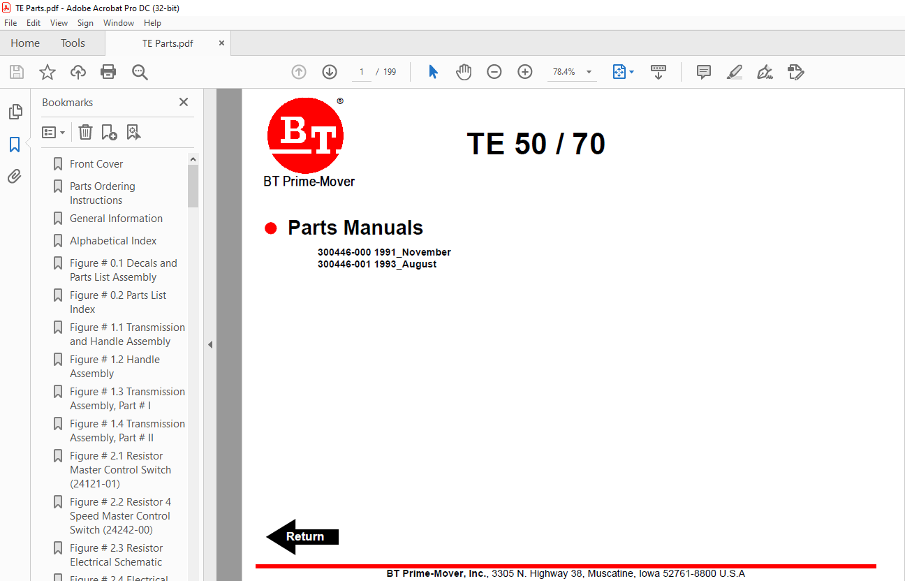
BT Prime-Mover Forklift TE-50/70 TE Series Electric Tow Tractor Part Manual – PDF DOWNLOAD
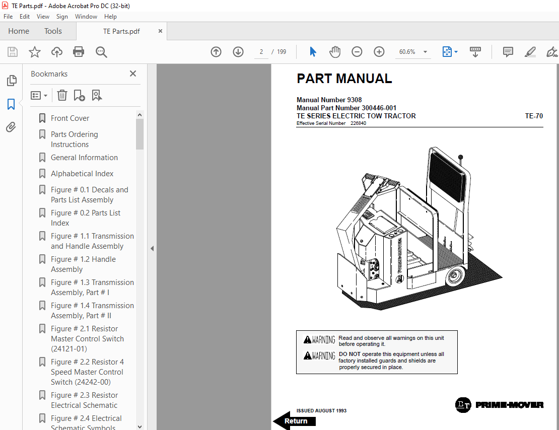
BT Prime-Mover Forklift TE-50/70 TE Series Electric Tow Tractor Part Manual – PDF DOWNLOAD
FILE DETAILS:
BT Prime-Mover Forklift TE-50/70 TE Series Electric Tow Tractor Part Manual – PDF DOWNLOAD
Language : English,
Pages :199
Downloadable : Yes
File Type : PDF
TABLE OF CONTENTS:
BT Prime-Mover Forklift TE-50/70 TE Series Electric Tow Tractor Part Manual – PDF DOWNLOAD
Front Cover 2
Parts Ordering Instructions 3
General Information 4
Alphabetical Index 5
Figure # 01 Decals and Parts List Assembly 7
Figure # 02 Parts List Index 9
Figure # 11 Transmission and Handle Assembly 11
Figure # 12 Handle Assembly 13
Figure # 13 Transmission Assembly, Part # I 15
Figure # 14 Transmission Assembly, Part # II 17
Figure # 21 Resistor Master Control Switch (24121-01) 19
Figure # 22 Resistor 4 Speed Master Control Switch (24242-00) 21
Figure # 23 Resistor Electrical Schematic 23
Figure # 24 Electrical Schematic Symbols 24
Figure # 25 Three Speed Control Wiring 25
Figure # 26 Three Speed Power Wiring 27
Figure # 27 Resistor Control Panel Assembly (24 Volt, 27259-09) 29
Figure # 28 Two/Three Speed Contactor Assembly (24 Volt, 27693-00) 31
Figure # 29 Forward & Rearward Contactor Assembly (24 Volt, 27692-00) 33
Figure # 210 Three Speed Contactor Panel Assembly (24 Volt, 27266-00) 35
Figure # 211 Fourth Speed Control Wiring (24 Volt) 37
Figure # 212 Fourth Speed Power Component Wiring (24 Volt) 39
Figure # 213 Fourth Speed Contactor Panel Assembly (27267-04) 41
Figure # 214 Contactor Assembly (24 Volt, 27158-01) 43
Figure # 215 Transistor Electrical Schematic 45
Figure # 216 Transistor Electrical Schematic Symbols 46
Figure # 217 Transistor Control Wiring Assembly 47
Figure # 218 Transistor Power Wiring 49
Figure # 219 Transistor Contactor Panel Assembly (24594-00, 24594-01) 51
Figure # 220 Contactor Assembly (27693-02) 53
Figure # 221 Power Connector Assembly 55
Figure # 222 Drive Motor Assembly (28500-00) 57
Figure # 223 Wiring Assembly for Cold Storage 59
Figure # 41 Cushion and Floor Mat Installation 61
Figure # 42 Shielding Installation 63
Figure # 43 Frame Assembly 65
Figure # 44 Automatic Coupler and Tow Eye Assembly 67
Figure # 101 Special Tools and Lubrication 69
Numerical Index 72
Back Cover 81
Front Cover 82
Parts Ordering Instructions 83
General Information 84
Alphabetical Index 85
Figure # 01 Decals and Parts List Assembly 87
Figure # 01 Parts List Index 89
Figure # 11 TE-50 Transmission and Handle Assembly 91
Figure # 12 TE-70 Transmission and Handle Assembly 93
Figure # 13 Handle Assembly 95
Figure # 14 TE-50 Transmission Assembly, Part # I 97
Figure # 15 TE-50 Transmission Assembly, Part # II 99
Figure # 16 TE-50 Drive Motor Assembly (Advanced 12 Volt 20190-01) (Prestolite 12 Volt 20190-00)101
Figure # 17 TE-70 Transmission Assembly, Part # I103
Figure # 18 TE-70 Transmission Assembly, Part II105
Figure # 21 Resistor Master Control Switch (24121-01)107
Figure # 22 Resistor 4 Speed Master Control Switch (24242-00)109
Figure # 23 EV-100 SCR Master Control Switch (24455-02)111
Figure # 24 TE-50 Resistor Electrical Schematic113
Figure # 25 TE-50 Electrical Schematic Symbols114
Figure # 26 TE-50 Two/Three Speed Control Wiring (12 Volt)115
Figure # 27 TE-50 Two/Three Speed Power Component Wiring117
Figure # 28 TE-50 Resistor Control Panel Assembly (12 Volt, 27259-08)119
Figure # 29 TE-50 Two Speed Contactor Assembly (12 Volt, 27693-01)121
Figure # 210 TE-50 Forward & Rearward Contactor Assembly (12 Volt, 27692-01)123
Figure # 211 TE-50 Three Speed Contactor Panel Assembly (12 Volt, 27058-01)125
Figure # 212 TE-50 Three Speed Contactor Assembly (12 Volt, 27158-00)127
Figure # 213 TE-70 Resistor Electrical Schematic129
Figure # 214 TE-70 Electrical Schematic Symbols130
Figure # 215 TE-70 Three Speed Control Wiring (24 Volt)131
Figure # 216 TE-70 Three Speed Power Wiring133
Figure # 217 TE-70 Resistor Control Panel Assembly (24 Volt, 27259-09)135
Figure # 218 TE-70 Two/Three Speed Contactor Assembly (24 Volt, 27693-00)137
Figure # 219 TE-70 Forward & Rearward Contactor Assembly (24 Volt, 27692-00)139
Figure # 220 TE-70 Three Speed Contactor Panel Assembly (24 Volt, 27266-00)141
Figure # 221 TE-70 Fourth Speed Control Wiring (24 Volt)143
Figure # 222 TE-70 Fourth Speed Power Component Wiring (24 Volt)145
Figure # 223 TE-70 Fourth Speed Contactor Panel Assembly (27267-04)147
Figure # 224 TE-70 Contactor Assembly (24 Volt, 27158-01)149
Figure # 225 TE-70 EV-100 SCR Electrical Schematic151
Figure # 226 TE-70 EV-100 SCR Electrical Schematic Symbols152
Figure # 227 TE-70 EV-100 SCR Control Wiring153
Figure # 228 TE-70 EV-100 SCR Two Speed Power Component Wiring155
Figure # 229 TE-70 EV-100 SCR Contactor Panel Assembly (27707-00)157
Figure # 230 TE-70 EV-100 Forward & Rearward Contactor Assembly (27692-00)159
Figure # 231 TE-70 EV-100 Forward & Rearward Contactor Assembly (27693-02)161
Figure # 232 TE-70 EV-100 SCR Panel Assembly163
Figure # 233 TE-70 EV-100 SCR Control Panel (27691-01)165
Figure # 234 Power Connector Assembly167
Figure # 235 TE-50, 12 Volt Drive Motor Assembly (R90-4001, 300280-000, Advanced)169
Figure # 236 TE-50, 12 Volt Drive Motor Assembly (MLD-4009, 20680-00, Prestolite)171
Figure # 237 TE-70, 24 Volt Drive Motor Assembly (27895-00, 5BC48JB471) GE173
Figure # 238 Wiring Assembly for Cold Storage175
Figure # 41 Cushion and Floor Mat Installation177
Figure # 42 Shielding Installation179
Figure # 43 Frame Assembly181
Figure # 44 Automatic Coupler and Tow Eye Assembly183
Figure # 101 Special Tools and Lubrications185
Numerical Index188
Back Cover199
IMAGES PREVIEW OF THE MANUAL:
More products