$38
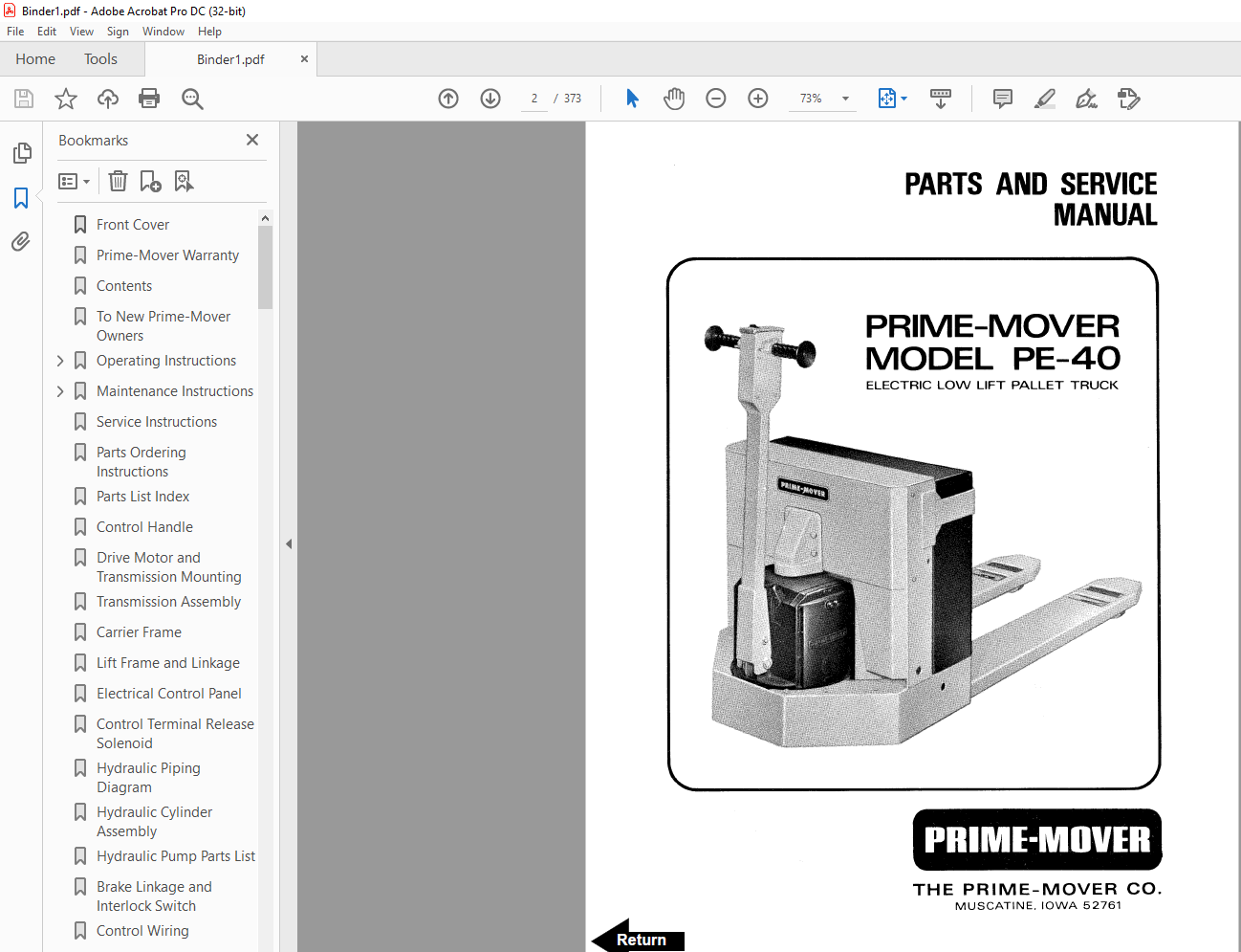
BT Prime-Mover PE-40 Electric Low Lift Truck Parts Manual – PDF DOWNLOAD
BT Prime-Mover PE-40 Electric Low Lift Truck Parts Manual – PDF DOWNLOAD
FILE DETAILS:
BT Prime-Mover PE-40 Electric Low Lift Truck Parts Manual – PDF DOWNLOAD
Language : English,
Pages :373
Downloadable : Yes
File Type : PDF
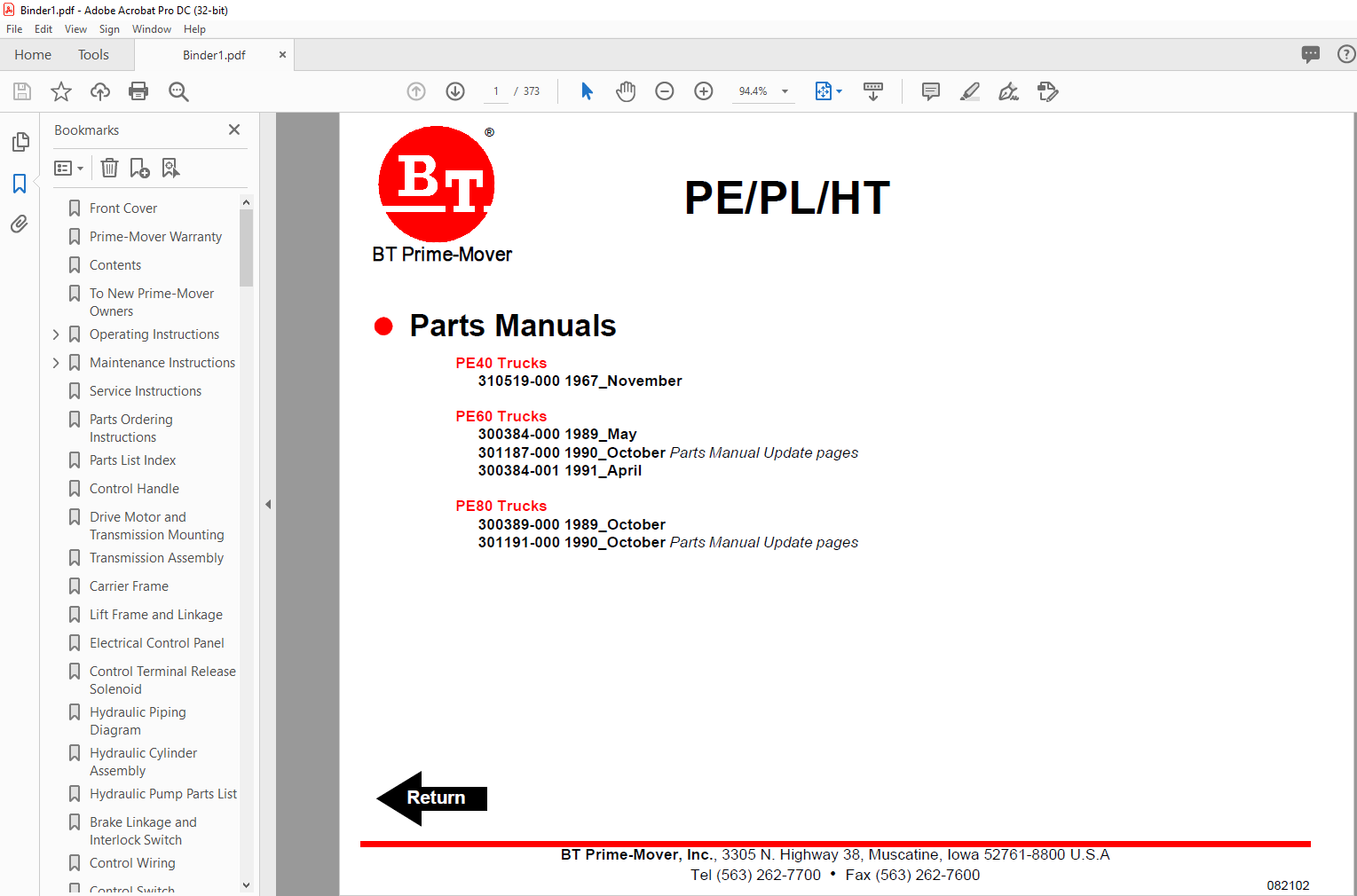
PE40 Trucks
310519-000 1967_November
PE60 Trucks
300384-000 1989_May
301187-000 1990_October Parts Manual Update pages
300384-001 1991_April
PE80 Trucks
300389-000 1989_October
301191-000 1990_October
TABLE OF CONTENTS:
BT Prime-Mover PE-40 Electric Low Lift Truck Parts Manual – PDF DOWNLOAD
Front Cover 2
Prime-Mover Warranty 3
Contents 4
To New Prime-Mover Owners 4
Operating Instructions 5
Preliminary Service 5
Controls 5
Safety Interlock 5
Lift/Lower 5
Direction Control 5
Deadman Brake 5
Key Switch (Optional) 5
Horn (Optional) 6
Dynamic Brake (Optional) 6
Operator Maintenance 6
Battery Care 6
Maintenance Instructions 7
Battery 7
Power Wiring 7
Control Wiring 7
Control Switches (Handle) 8
Limit Switch Adjustment (Lift) 8
Mechanical Brake 8
Interlock Switch 9
Transmission Rollers 9
Contactor Points 10
Motor Commutator 10
Hydraulic System 10
Service Instructions 11
Parts Ordering Instructions 11
Parts List Index 12
Control Handle 13
Drive Motor and Transmission Mounting 14
Transmission Assembly 16
Carrier Frame 17
Lift Frame and Linkage 18
Electrical Control Panel 19
Control Terminal Release Solenoid 20
Hydraulic Piping Diagram 21
Hydraulic Cylinder Assembly 21
Hydraulic Pump Parts List 22
Brake Linkage and Interlock Switch 23
Control Wiring 24
Control Switch Installation 25
Service Guide 27
Front Cover 30
Parts Ordering Instructions 31
General Information 32
Alphabetical Index 33
Figure # 01 Decals and Parts Assembly 35
Figure # 02 Parts List and Service Reference Index 37
Figure # 11 Transmission and Handle Assembly 39
Figure # 12 Handle Assembly 41
Figure # 13 22:1 Part # I Transmission Assembly 43
Figure # 14 Single Disc Brake Transmissions Assembly 45
Figure # 15 Drive Motor Assembly 47
Figure # 21 Resistor Master Control Switch 49
Figure # 22 EV-100/EV-1 SCR Master Control Switch 51
Figure # 23 Resistor Electrical Schematic 53
Figure # 24 Resistor Electrical Schematic Symbols 54
Figure # 25 Resistor Control Wiring Harness Assembly 55
Figure # 26 Third Speed Power Component Wiring 57
Figure # 27 Resistor Control Panel Assembly 59
Figure # 28 Contactor Assembly 61
Figure # 29 Forward & Rearward Contactor Assembly 63
Figure # 210 Third Speed Contactor Panel Assembly 65
Figure # 211 EV-100 SCR Trucks Electrical Schematic 67
Figure # 212 EV-100 SCR Truck Electrical Schematic Symbols 68
Figure # 213 EV-100 SCR Control Wiring 69
Figure # 214 EV-100 SCR Power Component Wiring 71
Figure # 215 EV-100 SCR Contactor Panel Assembly 73
Figure # 216 EV-100 SCR Forward & Rearward Contactor Assembly 75
Figure # 217 EV-100 1A Contactor Assembly 77
Figure # 218 EV-100 SCR Pump Contactor Panel Assembly 79
Figure # 219 EV-100 SCR Control Panel 81
Figure # 220 Power Connector Assembly 83
Figure # 221 Hydraulic Pump Motor Assembly 85
Figure # 222 Drive Motor Assembly 87
Figure # 223 Wiring Assembly for Cold Storage 89
Figure # 31 Hydraulic Schematic 91
Figure # 32 Hydraulic Schematic Symbols 92
Figure # 33 Hydraulic System 93
Figure # 34 Pump and Motor Assembly 95
Figure # 35 Lift Cylinder Assembly 97
Figure # 41 Shielding Assembly 99
Figure # 42 Carrier Frame Assembly101
Figure # 43 Caster Assembly103
Figure # 44 Lift Frame Assembly105
Figure # 45 Pallet Entry Rollers109
Figure # 46 Skid Adapter and Package Guard Assembly111
Figure # 47 Removable Load Backrest113
Figure # 61 Special Tools and Lubrications115
Numerical Index118
Back Cover131
Front Cover254
Parts Ordering Instructions255
General Information256
Alphabetical Index257
Figure # 01 Decals and Parts Assembly259
Figure # 02 Parts List and Service Reference Index261
Figure # 11 Transmission and Handle Assembly263
Figure # 12 Handle Assembly265
Figure # 13 22:1 Part # 1 Transmission Assembly267
Figure # 14 Part 2 22:1 Transmission Assembly269
Figure # 15 Drive Motor Assembly271
Figure # 21 Resistor Master Control Switch273
Figure # 22 EV-100/EV-1 SCR Master Control Switch275
Figure # 23 Resistor Electrical Schematic277
Figure # 24 Resistor Electrical Schematic Symbols278
Figure # 25 Resistor Control Wiring Harness Assembly279
Figure # 26 Third Speed Power Component Wiring281
Figure # 27 Resistor Control Panel Assembly283
Figure # 28 Contactor Assembly285
Figure # 29 Forward & Rearward Contactor Assembly287
Figure # 210 Third Speed Contactor Panel Assembly289
Figure # 211 EV-100 SCR Trucks Electrical Schematic291
Figure # 212 EV-100 SCR Truck Electrical Schematic Symbols292
Figure # 213 EV-100 SCR Control Wiring293
Figure # 214 EV-100 SCR Power Component Wiring295
Figure # 215 EV-100 SCR Contactor Panel Assembly297
Figure # 216 EV-100 SCR Forward & Rearward Contactor Assembly299
Figure # 217 EV-100 1A Contactor Assembly301
Figure # 218 EV-100 SCR Pump Contactor Panel Assembly303
Figure # 219 EV-100 SCR Control Panel305
Figure # 220 Power Connector Assembly307
Figure # 221 Hydraulic Pump Motor Assembly309
Figure # 222 Drive Motor Assembly311
Figure # 223 Wiring Assembly for Cold Storage313
Figure # 31 Hydraulic Schematic315
Figure # 32 Hydraulic Schematic Symbols316
Figure # 33 Hydraulic System317
Figure # 34 Pump and Motor Assembly319
Figure # 35 Lift Cylinder Assembly321
Figure # 41 Shielding Assembly323
Figure # 42 Carrier Frame Assembly325
Figure # 43 Caster Assembly327
Figure # 44 Lift Frame Assembly329
Figure # 45 Pallet Entry Rollers331
Figure # 46 Skid Adapter and Package Guard Assembly333
Figure # 47 Removable Load Backrest335
Figure # 61 Special Tools and Lubrications337
Back Cover339
Front Cover340
Alphabetical Index342
Figure # 16 PE-80 Resistor & Transistor Control Handle Assembly343
Figure # 21 Resistor Master Control Switch345
Figure # 224 PE-80 Transistor Electrical Schematic347
Figure # 225 PE-80 Transistor Electrical Schematic Symbols348
Figure # 226 PE-80 Transistor Control Wiring Harness Assembly349
Figure # 227 PE-80 Transistor Power Component Wiring351
Figure # 228 PE-80 Control Panel Assembly353
Figure # 229 Forward & Rearward Contactor Assembly355
Figure # 230 Power Connector Assembly357
Figure # 31 Hydraulic Schematic359
Figure # 32 Hydraulic Schematic Symbols360
Figure # 33 Resistor Hydraulic System361
Figure # 34 Pump and Motor Assembly363
Figure # 36 Transistor Hydraulic System365
Numerical Index368
Back Cover373
IMAGES PREVIEW OF THE MANUAL:
More products