$40
BT Prime-Mover RS/RR RS-20, RS-30, RS-40 Series Trucks Parts Manual – PDF DOWNLOAD
BT Prime-Mover RS/RR RS-20, RS-30, RS-40 Series Trucks Parts Manual – PDF DOWNLOAD
FILE DETAILS:
BT Prime-Mover RS/RR RS-20, RS-30, RS-40 Series Trucks Parts Manual – PDF DOWNLOAD
Language : English,
Pages :552
Downloadable : Yes
File Type : PDF
RS Series Trucks
310680-000 RS-40 OMP Manual 1970_September
310083-000 RS20/30/40 OMP Manual After March 01, 1974
302217-000 RS20/30/40 OMP Manual After March 01, 1974 with Serial Number 1504
RR Series Trucks
310509-000 1973_December
302215-000 RR-20/30 OMP Manual After March 01, 1974
302216-000 RR-30/20 OMP Manual After March 01, 1974 with Serial Number 1504
RS/RR Series Trucks
301074-000 1983_June
TABLE OF CONTENTS:
BT Prime-Mover RS/RR RS-20, RS-30, RS-40 Series Trucks Parts Manual – PDF DOWNLOAD
Front Cover 2
Warranty 3
New Owners 4
Contents 4
Operating Instructions 5
Maintenance Chart 7
Lubrication Chart 8
Maintenance Instructions 9
Service and Disassembly Instructions 13
Parts Ordering Instructions 16
Parts List Index 17
Main Frame, Shielding, Misc 19
Drive Mounting 21
24 Volt Transmission 23
Drive Motor Parts for D-25901 25
Brake Linkage 27
Steering Linkage 28
Steering Assembly 29
Steering Reduction 30
Single Pump Hydraulic Piping 31
Dual Pump Hydraulic Piping 33
Hydraulic Valve 35
Hydraulic: Valve Mounting, Reservoir Mounting, Motor Mounting 36
Hydraulic Pump 37
Pump Motor Assembly for P-25428 38
Tilt Cylinder Assembly 39
Adjusting Linkage 40
Lift Cylinder – White 3 Stage 41
Lift Cylinder Assembly – Prime-Mover 42
2 Stage Mast – Prime-Mover 43
3 Stage Mast – Knickerbocker 45
3 Stage Mast – White 47
GE Electrical Schematic 49
Square “D” Electrical Schematic 50
Power Wiring GE System 51
Power Wiring Square “D” 52
Control Wiring GE System 53
Control Wiring Square “D” System 54
Control Panel GE Electrical 55
Control Panel Square “D” SCR 56
Contactor Panel Square “D” System 57
Control Handle 58
Hour Meter 59
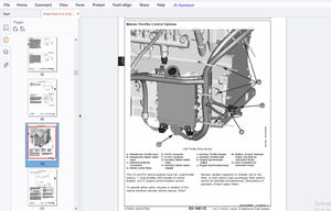
Auxiliary Hydraulic Valve 60
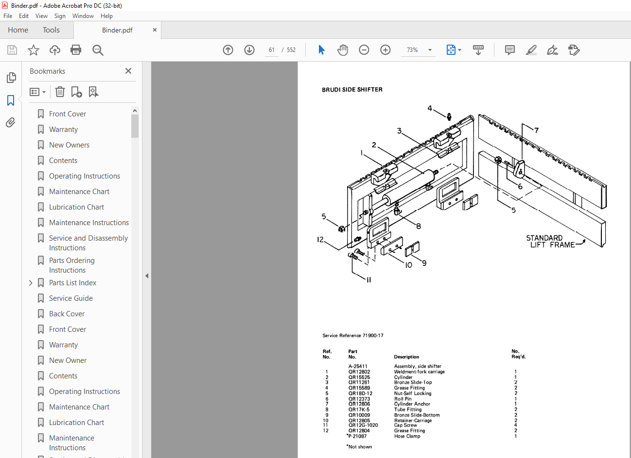
Brudi Side Shifter 61
Hydraulic Cylinder for Brudi Side Shifter 62
Brudi Hose Reel – Prime-Mover Masts 63
Brudi Hose Reel 64
Cascade Hose Reel Assembly for 3 Stage Masts 65
Spring Style Hose Reel 66
Service Guide 67
Back Cover 69
Front Cover 70
Warranty 71
New Owner 72
Contents 72
Operating Instructions 73
Maintenance Chart 75
Lubrication Chart 76
Manintenance Instructions 77
Service and Disassembly Instructions 81
Parts Ordering Instructions 84
Parts List Index 85
MainFrame, Shielding, Misc 87
Drive Mounting 89
24 Volt Transmission 91
Drive Motor Service Parts for D-25901 93
Notes 94
Brake Linkage 95
Steering Linkage 96
Steering Assembly 97
Steering Reduction 98
Hydraulic Piping for RR-20/30 99
Hydraulic Valve101
Hydraulic: Valve Mounting, Reservoir Mounting, Motor Mounting102
Hydraulic Pump103
Motor for P-25428 Pump/Motor Assembly104
Tilt Cylinder Assembly105
Adjusting Linkage106
Lift Cylinder White 3 Stage Mast107
Lift Cylinder Assembly108
Mast — 2 Stage109
White Masts111
GE Electrical Schematic113
Square D Electrical Schematic114
Power Wiring GE System115
Square D Power Wiring116
Control Wiring for GE System117
Control Wiring for Square D118
GE Electrical Control Panel119
SCR Control Panel — Square D System120
Contactor Panel Square D System121
Control Handle122
Hour meter123
Auxiliary Hydraulic Valve Parts Breakdown (4 function)124
Reach Attachment125
Brudi Hose Real Assembly for Prime-Mover Masts128
Brudi Hose Reel129
Cascade Hose Reel Assembly for 3 Stage Mast130
Outboard Spring Style Hose Reels131
Inboard Spring Style Hose Reels131
Service Guide132
Back Cover134
Front Cover135
Warranty136
New Owners137
Contents137
Specification137
Operating Rules and Instructions138
Maintenance Chart144
Lubrication Chart145
Maintenance Instructions146
Service and Disassembly Instructions150
Parts Ordering Instructions153
Parts List and Service Reference Index154
Main Frame, Shielding, Misc156
Drive Mounting158
24 Volt Transmission Service Parts160
Drive Motor Service Parts for D-25901162
Drive Motor Service Parts for D-25968163
Brake Linkage164
Steering Linkage165
Steering Assembly166
Steering Reduction167
Hydraulic Piping for RR-20/30170
Hydraulic Control Valve172
Hydraulic: Valve Mounting, Reservoir Mounting, Motor Mounting173
Hydraulic Pump for P-25428 Pump/Motor Assembly174
Motor for P-25428 Pump/Motor Assembly175
Tilt Cylinder176
Adjusting Linkage177
Lift Cylinder178
LiftCylinder Assembly — Prime-Mover180
Prime-Mover Mast — 2 Stage182
Reach Attachment Model RA184
Reach Attachment Model RD186
Knickerbocker TRI-FREE Roller — 3 Mast188
White Masts — Three Stage190
GE SCR Electrical Schematic — Model EV-1192
Electrical Schematic Symbols193
Control Wiring Ffor GE Model EV-1 System194
Power Wiring GE Model EV-1196
GE Model EV-1 Control198
Contactor Panel GE Model EV-1199
EV-1 Forward/Reverse Contactor200
EV-1 1A, P & FW Contactor202
Control Handle 204
Cold Storage Diagram/Components205
Auxiliary Hydraulic Valve Parts Breakdown207
rudi Side Shifter208
Hydraulic Cylinder for Brudi Side Shifter209
Brudi Hose Reel Assembly for Prime-Mover Masts210
Brudi Hose Reel211
Gleason Hose Reel Assembly for Three Stage Masts212
Gleason Hose Reel213
Service Guide214
Back Cover218
Front Cover219
Warranty220
New Oweners221
Operating Rules and Instructions222
Maintenance Chart228
Lubrication Chart229
Maintenance Instructions230
Service and Disassembly Instructions234
Parts Ordering Instructions237
Parts List and Service Reference Index238
Main Frame, Shielding, Misc240
Drive Mounting242
24 Volt Transmission Service Parts244
Drive Motor Service Parts for D-25901246
Drive Motor Service Parts for D-25968247
Brake Linkage248
Steering Linkage249
Steering Assembly250
Steering Reduction251
Hydraulic Piping Single Pump252
Hydraulic Piping Dual Pump254
Hydraulic Control Valve256
Hydraulic: Valve Mounting Reservoir Mounting Motor Mounting258
Hydraulic Pump for P-25428259
Motor for P-25428260
Tilt Cylinder261
Adjusting Linkage262
Lift Cylinder – 3 Stage White263
Lift Cylinder – Prime-Mover265
Mast – 2 Stage Prime-Mover267
Mast – 3 Stage Knickerbocker271
Mast – 3 Stage White273
GE SCR Elctrical Schematic Model EV-1275
Electrical Schematic Symbols276
Control Wiring for GE Model EV-1277
Power Wiring for GE Model EV-1279
GE Model EV-1 Control281
Contactor Panel GE Model EV-1282
Contactor Forward/Reverse, EV-1283
Contactor 1A, P, and FW, EV-1285
Control Handle, GE EV-1287
Cold Storage Diagram/Components288
Auxiliary Hydraulic Valve Parts Breakdown290
Brudi Side Shifter291
Hydraulic Cylinder for Brudi Side Shifter292
Brudi Hose Reel Assembly for Prime-Mover Masts293
Brudi Hose Reel294
Gleason Hose Reel Assembly for 3 Stage Masts295
Gleason Hose Reel300
Service Guide301
Back Cover305
Front Cover306
Prime-Mover Warranty307
Contents308
To New Prime-Mover Owners308
Operating Instructions309
Preliminary Service (Reach Truck)309
Operation309
Controls309
Key Switch309
Deadman Brake309
Direction Control309
Lift/Lower Control310
Tilt (Optional)310
Horn310
Auxiliary Hydraulic Controls310
Reach Control310
Operator Maintenance Instructions310
Battery Care310
Maintenance Instructions311
Battery311
Electrical Wiring311
Control Switches311
Deadman Brake311
Interlock Switch312
Steering Chain312
Transmission Rollers312
Contactor Points312
Motor Commutator312
Hydraulic System312
Hydraulic Valve Switch312
Lift Cylinder312
Lift Chain313
Tilt Cylinder313
Steering Linkage313
Articulating Plate Adjustment313
Reach Mechanism313
Service and Disassembly Instructions313
Reach Mechanism313
Mast313
Tilt Cylinder313
Mast Anchor Block314
Cylinder Hoses314
Hydraulic Lift Cylinder314
Floor Plate314
Transmission Assembly314
Articulating Plate314
Support Wheel Steering Linkage314
Support Wheels314
Load Wheels315
Drive Wheel315
Drive Motor315
SCR Panel315
SQ “D” Contactor Panel315
Steering Gear Box315
Lift Frame315
Inner Column315
Brake Disc315
Brake Cylinders315
Handle Assembly315
Parts Ordering Instructions316
Lubrication Chart316
Parts List Index317
Frame, Shielding and Wheels318
Drive Mounting320
Support Wheels321
Brake and Linkage322
Steering Assembly324
Steering Linkage325
Transmission Assembly328
Drive Motor Service Parts328
Power Wiring (SQ “D” System)329
SQ “D” SCR Panel330
SQ “D” Contactor Panel331
Control Wiring332
Schematic for Square D System333
Control Handle (GE and Square D)334
“GE” Electrical Control Panel335
Power Wiring (“GE” System)336
Control Wiring337
Schematic for GE System338
Hydraulic Piping340
Adjusting Linkage341
Tilt Cylinder Assembly (Optional)342
Hydraulic Pump and Motor (24V)343
Pump Motor Service Parts343
Hydraulic Valve (2 & 3 Spool)344
Mast (2 Stage)345
Lift Cylinder Assembly346
Lift Cylinder Assembly347
Sheave Head348
Reach Attachment350
Hose Reel & Fittings (Brudi)351
Hose Reel Assembly (Brudi)352
Mast, 3 Stage (White)354
Lift Cylinder – 3 Stage Mast355
Carriage (White) – 3 Stage Mast356
Hose Reel & Fittings (Aero-Motive)357
Hydraulic Swivel357
Hour Meter358
Battery Discharge Indicator358
Service Guide359
Back Cover365
Front Cover366
Warranty367
New Owners368
Contents368
Preliminary Service368
Operation Insutructions368
Operating Rules and Instructions369
Lubrication Chart374
Maintenance Instructions375
Service and Disassembly Instructions378
Parts Ordering Instructions390
RS20 Specifications391
RS30 Specifications392
RS40 Specifications393
RR20 Specifications394
RR30 Specifications395
Figure # 1 Decal and Parts Assembly397
Figure # 2 Parts List and Service Reference Index399
Figure # 3 Shielding Assembly402
Figure # 4 Drive Mounting404
Figure # 5 14:1 Transmission Assembly with MKU-4006 Drive Motor406
Figure # 6 Motor Assembly408
Figure # 7 Brake Linkage409
Figure # 8 Slave Cylinder Assembly411
Figure # 9 Master Cylinder Assembly412
Figure # 10 Steering Linkage413
Figure # 11 Steering Assembly414
Figure # 12 Power Steering Gear Box416
Figure # 13 Torque Generator417
Figure # 14 Forward Gear Reduction Steering Gear Box, Reverse Chain Reduction Steering Gear Box418
Figure # 15 GE Electrical Schematic – Model EV-1419
Figure # 16 Electrical Schematic Symbols420
Figure # 17 Wiring Harness Assembly421
Figure # 18 Power Component Assembly423
Figure # 19 SCR and Contactor Panel Assembly424
Figure # 20 EV-1 SCR Control425
Figure # 21 Transformer Assembly426
Figure # 22 Rectifier Heat Sink Assembly427
Figure # 23 GE Contactor Assembly428
Figure # 24 Power Steering Contactor Assembly429
Figure # 25 GE Contactor Assembly430
Figure # 26 Warning Light Assembly431
Figure # 27 Connector Assembly432
Figure # 28 Handle Assembly433
Figure # 29 Master Control Switch Assembly434
Figure # 30 Master Control Switch Assembly435
Figure # 31 Hydraulic Schematic436
Figure # 32 Hydraulic Schematic Symbols437
Figure # 33 Hydraulic Assembly (2 Stage)438
Figure # 34 Hydraulic Assembly – Part # 1439
Figure # 35 Tilt Cylinder Assembly and Related Parts441
Figure # 36 Tilt Cylinder Assembly442
Figure # 37 Lift Cylinder and Related Parts443
Figure # 38 2″ Lift Cylinder Assembly444
Figure # 39 2 1/2″ Lift Cylinder Assembly446
Figure # 40 2 3/4″ Lift Cylinder Assembly448
Figure # 41 Hydraulic Assembly (3 Stage)450
Figure # 42 Hydraulic Assembly (3 Stage) Part # 2451
Figure # 43 3 Stage Staging Cylinder Assembly453
Figure # 44 Freelift Cylinder Assembly454
Figure # 45 Hydraulic Assembly Part # 3455
Figure # 46 Pump and Motor Assembly456
Figure # 47 Motor Assembly457
Figure # 48 Power Steering Pump Assembly458
Figure # 50 Control Valve Assembly461
Figure # 51 Control Valve Assembly463
Figure # 52 Hydraulic Pump and Motor464
Figure # 53 Pump Assembly465
Figure # 54 Motor Assembly466
Figure # 55 Motor Assembly468
Figure # 56 Adjusting Linkage469
Figure # 57 2 Stage Mast Assembly470
Figure # 58 2 Stage Outer Column Assembly472
Figure # 59 2 Stage Inner Column Assembly473
Figure # 60 2 Stage Lift Cylinder and Related Parts475
Figure # 61 RS-30/40 Lift Frame and Load Backrest476
Figure # 62 RS-20 (Only) Lift Frame and Load Backrest477
Figure # 63 3 Stage Mast Assembly478
Figure # 64 Lift Frame Assembly479
Figure # 65 Inner Column Assembly (3 Stage)480
Figure # 66 Freelift Cylinder Assembly (3 Stage)481
Figure # 67 Intermediate Column Assembly (3 Stage)483
Figure # 68 Outer Column Assembly (3 Stage)484
Figure # 69 Fork Assembly485
Figure # 70 Auxiliary Hydraulic Valve Parts Breakdown486
Figure # 71 Brudi Sideshifter487
Figure # 72 Hydraulic Cylinder for Brudi Sideshifter488
Figure # 73 Gleason Hose Reel Assembly (3 Stage Masts)489
Figure # 74 Gleason Hose Reel 35 Series490
Figure # 75 Dual Elbow Swivel Assembly491
Figure # 76 Reach Attachment492
Figure # 77 Reach Attachment494
Figure # 78 Reach Attachment Hydraulic Assembly496
Figure # 79 Reach Attachment Cylinder Assembly497
Figure # 80 Load Wheel Assembly499
Troubleshooting Hydraulic Gear Pump500
Service Guide501
Back Cover504
Front Cover505
Prime Mover Warranty506
Contents507
To New Prime-Mover Owners507
Operating Instructions508
Preparation for Service508
Operation508
Controls508
Keyswitch508
Deadman508
Direction Control508
Lift-Lower Control508
Tilt508
Horn508
Auxiliary Hydraulic Controls508
Operator – Maintenance Instructions509
Daily509
Weekly509
Monthly509
Semi-Annually509
Annually509
Battery Care509
Maintenance Instructions510
Battery510
Electrical Wiring510
Control Switches510
Deadman Brake510
Interlock Switch510
Steering Chain511
Transmission Rollers511
Contactor Points511
Motor Commutator511
Hydraulic System511
Hydraulic Valve Switch511
Lift Cylinder511
Lift Chain511
Tilt Cylinder511
Steering Linkage511
Service Instructions513
Mast513
Tilt Cylinder513
Hydraulic Reservoir513
Cylinder Hoses513
Hydraulic Lift Cylinder513
Floor Plate513
Transmission Assembly513
Support Wheel Steering Linkage514
Support Wheels514
Load Wheels514
Drive Wheel514
Drive Motor514
SCR Panel514
Sq “D” Contactor Panel514
Steering Gear Box514
Lift Frame514
Inner Column514
Brake Disc514
Brake Cylinders514
Handle Assembly514
Parts Ordering Instructions516
Lubrication Chart519
Major Parts Listing520
Stacker Frame Parts521
Mast Assembly Parts List523
Transmission Assembly525
Drive Mounting526
Lift Cylinder527
Tilt Cylinder528
Hydraulic Valve529
Hydraulic Piping531
Hydraulic Pump and Motor532
Handle533
Brake and Linkage534
Steering Linkage535
Steering537
Support Wheels538
Load Wheel539
Sheave Head539
Power Wiring540
Sq “D” SCR Panel542
Sq “D” Contactor Panel543
Control Wiring546
Service Guide550
Back Cover552
IMAGES PREVIEW OF THE MANUAL:
More products