$45
CARTER THERMO QUAD SERVICE MANUAL – PDF DOWNLOAD
CARTER THERMO QUAD SERVICE MANUAL – PDF DOWNLOAD
IMAGE PREVIEW:

CARTER THERMO QUAD SERVICE MANUAL

CARTER THERMO QUAD SERVICE MANUAL
DESCRIPTION:
CARTER THERMO QUAD SERVICE MANUAL – PDF DOWNLOAD
- The Carter Thermo-Quad was one of the first new type carburetors designed to help reduce exhaust emissions wilhout sacrificing the maximum p e r formance that high-output engines were capable of deliver ing.
- The design innovations Incorporated in the Thermo-Quad provide a much higher degree of temperature control. The results were so effective that the Th’ermo-Quad runs as much as 20′ cooler than all metal carburetors.
- Periormance oriented technicians understand immediately that a cooler carburetor keeps the fuel in the liqu Id state where it is supposed to be liquid – and vaporized when supposed to be vapor.
- He also knows that heat expands both liquid and vapor, and that a ··cooler-fed'” engine will prod uce more power. Expansion should occur inside an engine – not outside.
- 2 STIPUP -Pl.ATE Three basic assemblies make up the ThermoQuad: the throttle body, fuel bowl and bowl cover. The throttle body is a high-grade aluminum casting and contains the throttie vaives, linkages, idle mixture screws. and various vacuum ports and external tubes.
- The bowl cover is also an aluminum casting and contains essentially all metering compone.nts. Between the throttle body and bowl cover ,s a phenolic resin fuel bowl that possesses very high insulating characteristics.
- Consequently, heat from the engine which would normally envelop the entire carburetor is blocked by th·e fuel bowl, thus permitting the metering section (bowl cover) to remain much cooler than conventional all metal carburetors.
TABLE OF CONTENTS:
CARTER THERMO QUAD SERVICE MANUAL – PDF DOWNLOAD
Description. . . . . . . . . . . . . . . . . . . . . . . . . . . . . . . . . . . . . . . . . . . . . . . . . . . . . . 2
Float Circuit. . . . . . . . . . . . . . . . . . . . . . . . . . . . . . . . . . . . . . . . . . . . . . . . . . . . . 3
Bowl Vents. . . . . . . . . . . . . . . . . . . . . . . . . . . . . . . . . . . . . . . . . . . . . . . . . . 4
Bowl ……………………………………………….. 5
Low Speed Circuit. . . . . . . . . . . . . . . . . . . . . . . . . . . . . . . . . . . . . . . . . . . . . . . . 5
Swept Idle Air. . . . . . . . . . . . . . . . . . . . . . . . . . . . . . . . . . . . . . . . . . . . . . . . 6
Mixture Screws. . . . . . . . . . . . . . . . . . . . . . . . . . . . . . . . . . . . . . . . . . . . . . . 6
By-Pass Assist. . . . . . . . . . . . . . . . . . . . . . . . . . . . . . . . . . . . . . . . . . . . . . . 6
Idle Restrictors. . . . . . . . . . . . . . . . . . . . . . . . . . . . . . . . . . . . . . . . . . . . . . . 7
Idle Enrichment System. . . . . . . . . . . . . . . . . . . . . . . . . . . . . . . . . . . . . . . . 7
Hot Idle Compensator. . . . . . . . . . . . . . . . . . . . . . . . . . . . . . . . . . . . . . . . . 8
Idle Solenoids. . . . . . . . . . . . . . . . . . . . . . . . . . . . . . . . . . . . . . . . . . . . . . . . 8
Transducer And Ground Switch. . . . . . . . . . . . . . . . . . . . . . . . . . . . . . . . . . . . . 8
Dash pot……………………………………………….. 9
Primary High Speed Circuit ………………………………… ,. 9
Diminishing Well Bleed. . . . . . . . . . . . . . . . . . . . . . . . . . . . . . . . . . . . . . . . 10
Quad X Rings. . . . . . . . . . . . . . . . . . . . . . . . . . . . . . . . . . . . . . . . . . . . . . . . 11
Secondary High Speed Circuit. . . . . . . . . . . . . . . . . . . . . . . . . . . . . . . . . . . . . . 11
Air Valve Dashpot ……………… · . . . . . . . . . . . . . . . . . . . . . . . . . . . 12
Alcomp System . . . . . . . . . . . . . . . . . . . . . . . . . . . . . . . . . . . . . . . . . . . . . . . . . . 12
Pump Circuit. . . . . . . . . . . . . . . . . . . . . . . . . . . . . . . . . . . . . . . . . . . . . . . . . . . . 13
Two Stage Pump. . . . . . . . . . . . . . . . . . . . . . . . . . . . . . . . . . . . . . . . . . . . . 13
Choke Circuit ……………………………………………. · 14
Choke Pull-Off And Modulator Spring. . . . . . . . . . . . . . . . . . . . . . . . . . . . . 14
Tamper Proof Choke Pull-Off. . . . . . . . . . . . . . . . . . . . . . . . . . . . . . . . . . . 14
Cross Over Choke. . . . . . . . . . . . . . . . . . . . . . . . . . . . . . . . . . . . . . . . . . . . 15
Integral Choke ……………………………………….. 15
Electric Assist Choke. . . . . . . . . . . . . . . . . . . . . . . . . . . . . . . . . . . . . . . . . . 15
Vacuum Pull-Off Choke ………………………………… ·. 16
Fast Idle And Unloader. . . . . . . . . . . . . . . . . . . . . . . . . . . . . . . . . . . . . . . . 16
Throttle Positioner Solenoid . . . . . . . . . . . . . . . . . . . . . . . . . . . . . . . . . . . . . . . . 16
Purge Ports ………………….·. . .. .. .. . . . .. . .. .. .. . . . . .. . . . . . 17
Vacuum Connections. . . . . . . . . . . . . . . . . . . . . . . . . . . . . . . . . . . . . . . . . . . . . . 17
Hose Connections 1976-1977. . . . . . . . . . . . . . . . . . . . . . . . . . . . . . . . . . . . . . . 18
Hose Connections 1978 thru 1982 . . . . . . . . . . . . . . . . . . . . . . . . . . . . . . . . . . . 19
02 Feedback System ………. -……………………………… 20
Pulse Width Modulation. . . . . . . . . . . . . . . . . . . . . . . . . . . . . . . . . . . . . . . . 21
Checking Pulse Solenoid. . . . . . . . . . . . . . . . . . . . . . . . . . . . . . . . . . . . . . . 21
Parts List . . . . . . . . . . . . . . . . . . . . . . . . . . . . . . . . . . . . . . . . . . . . . . . . . . . . . . . 22
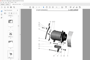
Exploded View . . . . . . . . . . . . . . . . . . . . . . . . . . . . . . . . . . . . . . . . . . . . . . . . . . . 23
Adjustments. . . . . . . . . . . . . . . . . . . . . . . . . . . . . . . . . . . . . . . . . . . . . . . . . . . . . 24
More products