$45
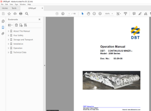
CAT Bucyrus CONTINUOUS MINER 25M Series Operation Manual 03-29-05 - PDF DOWNLOAD
CAT Bucyrus CONTINUOUS MINER 25M Series Operation Manual 03-29-05 - PDF DOWNLOAD
FILE DETAILS:
CAT Bucyrus CONTINUOUS MINER 25M Series Operation Manual 03-29-05 - PDF DOWNLOAD
Language :English
Pages :150
Downloadable : Yes
File Type : PDF
IMAGES PREVIEW OF THE MANUAL:
DESCRIPTION:
CAT Bucyrus CONTINUOUS MINER 25M Series Operation Manual 03-29-05 - PDF DOWNLOAD
preface
- This manual is intended to provide basic operating information on DBT 25M Series class continuous miners. Additional information can be obtained by referring to the Parts Book supplied with your machine, or by contacting your local DBT representative.
- The illustrations, descriptions and procedures contained in this manual pertained to the machine as it was originally manufactured and delivered to your mine, and when the manual was approved for printing. DBT reserves the right to discontinue or revise machine models at any time, or change specifications, designs or procedures, without notice and without incurring obligations.
- The machine was manufactured under the guidelines, procedures and requirements of the appropriate government regulatory agencies. At the completion of manufacturing, this machine was issued the appropriate approval numbers and nameplates indicating that it met the technical requirements of the appropriate agencies. Any change to the design or structure of this machine, without the consent of DBT and these agencies, may void these approvals and render the machine illegal or dangerous for use.
- Strict compliance with all local and national laws, regulations and practices regarding the safe operation and maintenance of underground mining equipment is necessary to ensure the personal safety of those working on, or around, this machine. While this manual attempts to anticipate the most important operations and maintenance needs for this equipment, unforeseen circumstances may arise that have not been addressed in this manual.
- If any concerns or questions arise, please contact your DBT America Service Representative immediately. This work contains information protected under trade secret and other intellectual property laws, and is protected under the U. S. Copyright Act of 1976, as amended. This work is provided under license and the license is non-transferable. Distribution and access is limited only to authorized personnel. Disclosure, reproduction, distribution or unauthorized use may be a violation of federal and state laws and may subject the unauthorized user to criminal liability.
TABLE OF CONTENTS:
CAT Bucyrus CONTINUOUS MINER 25M Series Operation Manual 03-29-05 - PDF DOWNLOAD
About This Manual 9
Right Operating Manual 11
Type 11
New Operating Manual 11
Efficiency 12
Service 12
Safety 12
Your Safety 13
State of the Art 15
Further Operating Manuals 15
Safety Precautions 16
Training 16
Operating Conditions 17
Storage and transport 18
Pre-Start Inspection 18
Operation 18
Inspection 18
Maintenance 18
Instruction and Safety 18
Operator's Compartment 18
Canopy 18
Stopping 19
Operator's Compartment 19
Parking 19
Securing 19
Replacing Components 19
Original Parts 19
Lifting 19
Handling Hydraulic Fluids 19
Permissible Hoses 20
Storage and Transport 23
Corrosion Protection 25
No Direct Exposure to Sunlight 25
Short Term Storage 25
Long Term Storage 25
Plastic Deformation 26
Random Sample Inspection 26
Natural Aging 26
HFA Fluids 26
Before Transport 26
Temperature Below Freezing 27
Antifreeze Measures for Oil Cooler 27
Electrical and Electronic Components 27
Installation 29
Special Tools 31
General Safety Rules 32
General Safety Maintenance 33
Lubricate Every Shift 35
Inspect Daily 35
Lubricate Weekly 35
Lubricate Daily 35
Check Daily 36
Replace When Necessary 36
Electric Motor Maintenance 36
Every Month 36
Electric Motor Maintenance 38
Every Three Months 38
Every Six Months 38
Annually 38
Notes on Installation 39
Installation Plan 39
Supper Bolt Installation & Specifications 40
Tightening Procedures 40
Loosening Procedures 41
Lubicants 42
Safety Features 44
Panic Strip (s) 44
Canopy 44
Fire Suppression 44
Guards and Covers 44
Circuit Breaker Reset 44
Operation 45
Cutting Head Assembly 47
Cutting Support Frame Pivot Pin 48
Drum Drive Torque Limiting Switch 49
Drum Drive Motor: 25M0 & 25M1 49
Drum Drive Motor: 25M2 & 25M3 50
Shear Cylinder: 25M0, 25M1 & 25M2 51
Shear Cylinder: 25M3 52
25M0 Cutting Drum Installation & Removal 52
Center Cutting Drums 52
End Cutting Drums 53
Main Cutting Drums 53
25M1 Cutting Drum Installation & Removal 54
Center Cutting Drum 54
End Cutting Drum 55
Main Cutting Drum 55
25M2 / 25M3 Cutting Drum Installation & Removal 56
End Cutting Drum 57
Center Cutting Drum 58
End Cutting Drum 58
25M0 Drum Drive Gear Case Installation / Removal 59
Figure 21 / 25M0 62
25M1 Drum Drive Gear Case Installation / Removal 60
Figure 22 / 25M1 63
25M2 / 25M3 Drum Drive Gear Case Installation / Removal 61
Figure 23 / 25M2 / 25M3 64
Gathering Head Assembly Installation / Removal 65
CLA Installation / Removal 66
Gathering Head Motor Installation / Removal 67
Foot Shaft Installation / Removal 67
Gear Case Installation / Removal 68
Lift Cylinder Installation / Removal 69
Tram Case Installation / Removal From Tractor Frame 70
Tram Sprocket Installation / Removal 75
Crawler Front Idler Installation / Removal 78
Crawler Chain Tension Adjustment 76
Crawler Chain Take-Up Jack Assembly 79
Tram Planetary Installation / Removal 71
Tram Secondary Planetary Installation / Removal 72
Tram Case Installation / Removal 73
Stabilizing Cylinder Installation / Removal 74
Hydraulic Pump Installation / Removal 79
Hydraulic Pump Motor Installation / Removal 80
Conveyor Assembly Installation / Removal 81
Conveyor Lift Cylinder Installation / Removal 85
Tail Conveyor Shim Adjustment 84
Tail Roller Installation / Removal 84
Conveyor Swivel Pin Installation / Removal 83
Swing Cylinder Installation / Removal 82
Conveyor Chain Installation / Removal 86
Conveyor Chain Tension Adjustment 86
Scrubber System 88
Scrubber Motor 89
Scrubber Cleaning 89
Electrical Components 90
Power Schematic 90
Motor Overloads 90
Motor Control 91
Cutting Motor Feedback 91
Radio Control Schematic 92
Tram Dead Man Switch 92
Methane Monitor 93
Low Oil Level Switch 93
E-Stop Bypass 93
Battery Back-Up System 93
Scrubber Fan 93
Cutting Motor Feedback Adjustment 94
Armature Voltage 95
Radio Remote Control 96
Receiver, Power Supply & Tram Case Module 96
Diagnostic Display 97
Radio Transmitter 97
Batery Charger 97
Permissibility 97
Trouble Shooting 98
Dual Systems 98
Diagnostic Display 99
Component Change Out 99
Technical Data 101
Tractor Frame (Figure 1) 104
Tram Motor (Figure 2) 105
Tram In-Put Planetary (Figure 3) 106
Tram Secondary Planetary (Figure 4) 107
Tram Case (Figure 5) 108
Tram Case (Figure 6) 109
Stabilizing Cylinder (Figure 7) 110
Tram Sprocket (Figure 8) 111
Crawler Chain Adjustment (Figure 9) 112
Crawler Front Idler (Figure 10) 113
Crawler Take-Up Jack (Figure 11) 114
Hydraulic Pump (Figure 12) 115
Hydraulic Pump Motor (Figure 13) 116
Gathering Head (Figure 14) 117
Gathering Head Assembly (Figure 15) 118
Gathering Head CLA Installation / Removal (Figure 16) 119
Gathering Head Motor Installation / Removal (Figure 17) 120
Gathering Head Foot Shaft Installation / Removal (Figure 18) 121
Foot Shaft Assembly (Figure 19) 122
Gathering Head Gear Case Installation / Removal (Figure 20) 123
Gathering Head Gear Case Assembly (Figure 21) 124
Gathering Head Gear CaseAssembly (Figure 22) 125
Gathering Head Lift Cylinder Installation / Removal (Figure 23) 126
Cutting Head Assembly (Figure 24) 127
Cutting Head Support Frame Assembly (Figure 25) 128
Cutting Head Pivot Pin 25M0 / 1 / 2 (Figure 26) 129
Cutting Head Pivot Pin 25M3 (Figure 27) 130
Cutting Head Torque Limiting Clutch 25M2 & 25M3 (Figure 28) 131
Cutting Head Motor 25M2 & 25M3 (Figure 29) 132
Cutting Head Motor 25M0 & 25M1 (Figure 30) 133
Cutting Head Shear Jack 25M0, 25M1 & 25M2 (Figure 32) 134
Cutting Head Shear Jack 25M3 (Figure 33) 135
Drum Drive Gear Case 25M0 (Figure 34) 136
Drum Drive Gear Case 25M1 (Figure 35) 137
Drum Drive Gear Case 25M2 (Figure 36) 138
Drum Drive Gear Case 25M3 (Figure 37) 139
Conveyor (Figure 38) 140
Conveyor (Figure 39) 141
Swing Cylinder (Figure 40) 142
Conveyor Swivel Pin (Figure 41) 143
Conveyor Tail Roller (Figure 42) 144
Tail Conveyor Shim Set (Figure 43) 145
S.M 30/3/2025
More products