$45
Cat BUCYRUS CONTINUOUS MINER 30M-3 Spare Parts Manual - PDF DOWNLOAD
Cat BUCYRUS CONTINUOUS MINER 30M-3 Spare Parts Manual - PDF DOWNLOAD
FILE DETAILS:
Cat BUCYRUS CONTINUOUS MINER 30M-3 Spare Parts Manual - PDF DOWNLOAD
Language :English
Pages :903
Downloadable : Yes
File Type : PDF
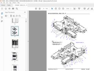
IMAGES PREVIEW OF THE MANUAL:
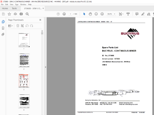

DESCRIPTION:
Cat BUCYRUS CONTINUOUS MINER 30M-3 Spare Parts Manual - PDF DOWNLOAD
Spare Parts List
BUCYRUS - CONTINUOUS MINER
ID - No.:373608
Serial number: 197854
Jim Walters Resources Inc. #4 Mine
30M-3
GENERAL SAFETY
- FREQUENT INSPECTION SHALL BE MADE. ALL ELECTRICAL PARTS, INCLUDING THE PORTABLE CABLE AND WIRING, SHALL BE KEPT IN A SAFE CONDITION. THERE SHALL BE NO OPENINGS INTO THE CASINGS OF THE ELECTRICAL PARTS. A PERMISSIBLE DISTRIBUTION BOX SHALL BE USED FOR CONNECTION TO THE POWER CIRCUIT UNLESS CONNECTION IS MADE IN FRESH INTAKE AIR.
- TO MAINTAIN THE OVERLOAD PROTECTION ON DIRECT CURRENT MACHINES, THE UNGROUNDED CONDUCTOR OF THE PORTABLE CABLE SHALL BE CONNECTED TO THE PROPER TERMINAL. THE MACHINE FRAME SHALL BE EFFECTIVELY GROUNDED. THE POWER WIRES SHALL NOT BE USED FOR GROUNDING EXCEPT IN CONJUNCTION WITH DIODE(S) OR EQUIVALENT. THE OPERATING VOLTAGE SHOULD MATCH THE VOLTAGE RATING OF THE MOTOR(S).
TABLE OF CONTENTS:
Cat BUCYRUS CONTINUOUS MINER 30M-3 Spare Parts Manual - PDF DOWNLOAD
Spare Parts List
BUCYRUS - CONTINUOUS MINER
ID - No.:373608
Serial number: 197854
Jim Walters Resources Inc. #4 Mine
30M-3
SECTION 1 HOW TO TROUBLESHOOT THIS SYSTEM 1
SECTION 2 SYSTEM STATUS INDICATORS 3
2 1 Introduction 3
2 2 Status LED Functional Categorization 3
2 3 Status LED Response Analysis 6
SECTION 3 ALARMS, WARNINGS, AND DISPLAY INFORMATION 21
3 1 Coded Alarms and Warnings 22
3 1 1 Alarm Codes 22
3 1 2 Warning Codes 24
3 2 Informational Messages 29
SECTION 4 COMPONENT IDENTIFICATION 31
4 1 Remote Control System Components 31
4 2 Remote Control System Components Tie-in 31
Manual Contents
List of Tables
Table Page
Table 2 1 MCU944 LED Functional Categories 5
Table 2 2a MCU944 Status LED Response Analysis (Rl & R2) 6
Table 2 2b MCU944 Status LED Response Analysis (R3 & R4) 7
Table 2 2c MCU944 Status LED Response Analysis (R5 & R6) 8
Table 2 2d MCU944 Status LED Response Analysis (Rl 1 & R12) 9
Table 2 2e MCU944 Status LED Response Analysis (R13 & R14) 11
Table 2 2f MCU944 Status LED Response Analysis (Rl 5 to R20) 11
Table 2 2g MCU944 Status LED Response Analysis (R21 & R22) 12
Table 2 3 TX944 Status LED Response Analysis 13
Table 2 4 RX944 Status LED Response Analysis 17
Table 2 5 CPS944 Status LED Response Analysis 18
Table 2 6 DCD 100 Status LED Response Analysis 19
Table 3 1 Display Screen Top Banner General Description 21
Table 3 2 Alarm Codes 22
Table 3 3 Warning Codes 24
Table 3 4 Informational Messages 29
Table 4 1 System Components 31
List of Figures
Figure Page
Figure 2 1 MCU944 Custom PLC Status LEDs 3
Figure 2 2 TX944 Transmitter Status LEDs 13
Figure 2 3 RX944 Receiver Status LEDs 17
Figure 2 4 CPS944 Power Supply Status LEDs 18
Figure 2 5 DCDl00 DC Tram Drive Status LEDs 19
Figure 3 1 Display Screen Messages 21
Figure 4 1 Remote Control System Components Layout 32
S.M 31/3/2025

