$35
CAT DBT - Main filter station Operating Manual - PDF DOWNLOAD
CAT DBT - Main filter station Operating Manual - PDF DOWNLOAD
FILE DETAILS:
CAT DBT - Main filter station Operating Manual - PDF DOWNLOAD
Language :English
Pages :68
Downloadable : Yes
File Type : PDF
IMAGES PREVIEW OF THE MANUAL:
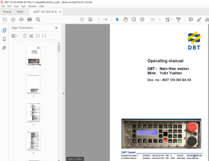
TABLE OF CONTENTS:
CAT DBT - Main filter station Operating Manual - PDF DOWNLOAD
Doc. no.: 4007 135 050 BA 00
Contents
1 About this manual
Before starting work 1 5
Characters and symbols used 1 6
2 Your safety
Further operating manuals 2 3
Personnel 2 3
Installation and repair 2 3
Operating conditions 2 4
Intended use 2 4
Unauthorized use 2 4
Surrounding area conditions 2 4
Prerequisites for operation 2 4
Safety instructions 2 5
3 Storage and transport
Storage 3 3
Storage of the equipment 3 3
Transport 3 3
Before transport 3 3
Transport containers, dimensions and weights 3 3
4 Installation
Main filter station 4 5
5 Operation
The PMC®-R control unit 5 3
Maintenance of the computers 5 3
Tightening the mounting bolts 5 3
System overview 5 4
General information 5 4
System overview 5 4
The PMC®-R control computer 5 4
Operation of the PMC®-R control unit 5 4
The PMC®-R control unit; overview of the keyboard and
menu functions 5 4
Keyboard assignment of PMC®-R program 5 5
Changing program parameters 5 7
Display 5 8
At rest display 5 8
Emergency stop 5 8
DBT GmbH, Lünen 2005
Contents
DBT - PMC®-R
Local shield blocking switch (black) 5 9
Display of unconnected or defective sensors 5 9
Menu structure in the PMC®-R
(columns from left to right) 5 9
Menu call ups through menu keys 5 12
Menu call ups through speed-dialing keys 5 12
Overview of the menu displays: 5 14
Manual and semi-automatic functions 5 15
Manual control of the system 5 15
Enabling automatic sequence operation 5 15
Interrupting and switching off the automatic
sequence functions 5 16
The function of the local blocking switch 5 16
The function of the emergency stop switch 5 16
The automatic sequence functions 5 17
MEASUREMENT VALUES 5 18
HFS PARAMETER 5 19
ERROR MESSAGES 5 21
SERVICE 5 22
DIAGNOSTICS 5 24
BLOCKING FUNCTIONS 5 26
Saved error messages 5 27
Meaning of the LED displays 5 27
6 Technical data
The PMC®-R control system 6 3
System overview 6 3
Rear side of the PMC®-R 6 4
Plug connections for Face-PMC®-R 6 4
Code plug 6 4
Code plug SKK24 6 4
Valve-strip pin connections 6 6
Power supply 6 8
Sensors 6 9
Pressure sensor 6 9
Hose cable between valve strip and PMC®-R 6 11
VALVE CABLE 6 12
Line SKK24 - SKK24 6 14
7 For your information
Our service 7 3
Service addresses 7 3
DBT GmbH, Lünen 2005
S.M 1/4/2025
More products